Universal Material
The Universal material puts Substance maps and PBR outputs into OctaneRender®. Substance Painter and other engines map well to this material. Universal materials blend between dielectric and metallic with a Metallic parameter value from 0 - 1. Compared to other materials, the Universal material is equivalent to the Metallic material when its Metallic parameter is set to 1.0, and it is similar to the Glossy material when its Metallic parameter is set to 0.0.
The Universal material is designed to follow after the workflow in the PBR model, since the Metallic material falls short of the metallic and roughness maps that are often derived from Substance Painter and other tools. The Universal material handles dielectric material (Diffuse and Glossy BRDF) and also Metallic material (Glossy BRDF) with assumed IOR or custom IOR for both dielectric and metallic surfaces. Material IOR in the base layer of Universal materials is also not limited to scalar values, and this can be controlled procedurally with texture-type nodes and OSL shaders connected to a new IOR texture input pin.
|
|
Universal Material
|

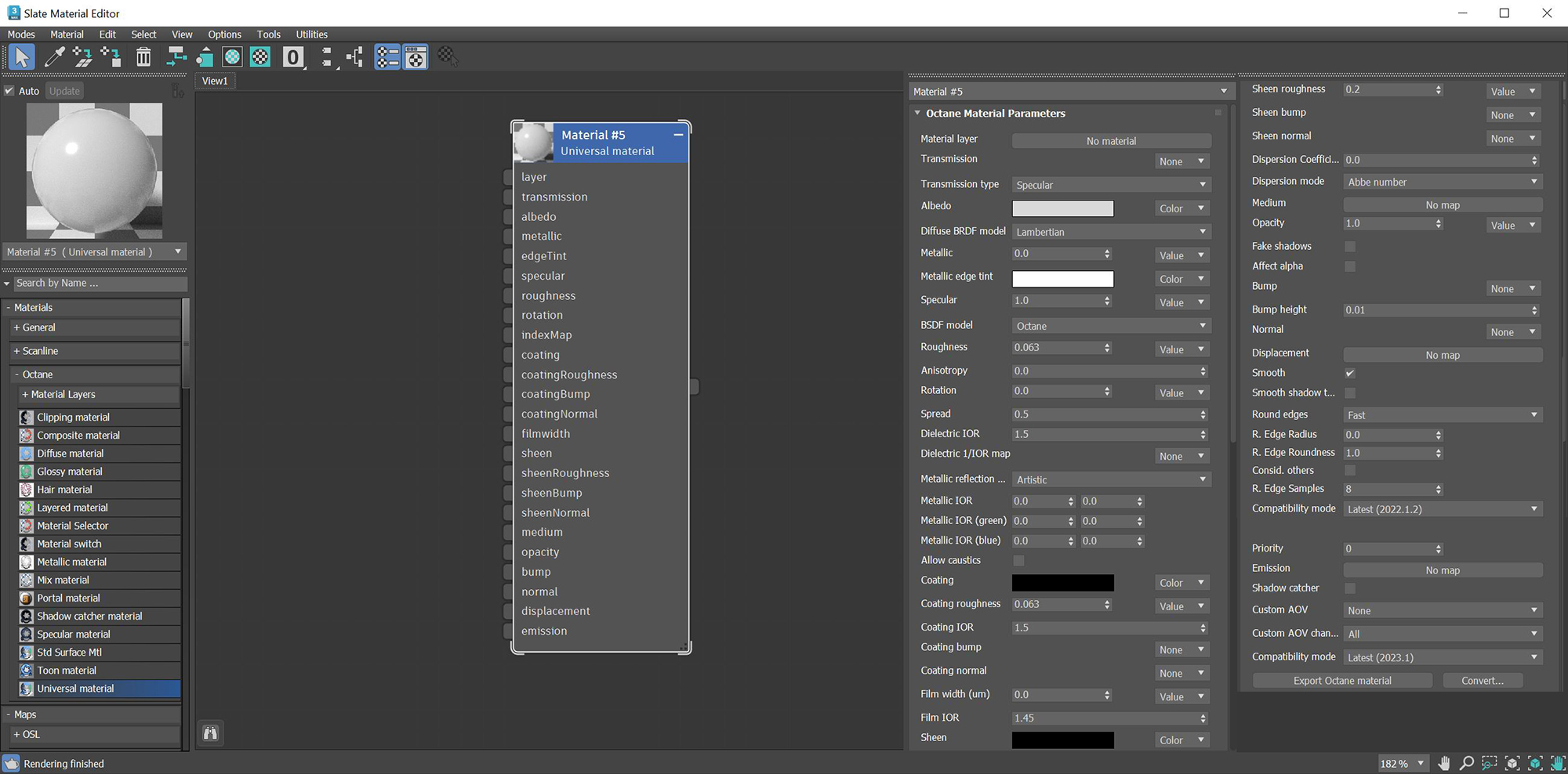
Figure 1: The Universal material parameters
|
|
Universal Material
|
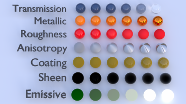
Figure 2: Creating basic and complex materials with Universal materials
You can also import the Base Color maps, Height maps, Normal maps, Occlusion maps, and other texture maps for a scene derived from major 3D painting software into OctaneRender, and then re-link these texture maps to the corresponding Universal material node pins. The Universal material node blends the Glossy and Metallic materials, depending on the Metallic input settings. You can then adjust each texture's settings in greater detail. For example, you can place real-world IOR values of Metallic objects as part of the Universal material's Red, Green, and Blue IOR metallic input channels.
Universal Material Parameters
Material Layer - Adds a material layer above the base layer. See the Material Layers topic in this manual for more details.
Transmission - Controls how light passes through a transparent surface. It is tied with the Dielectric IOR parameter to control surface transparency. It accepts a Color, Texture, or value as an input, but Color input provides the most control. To create colored glass, change the Color input to something other than black and set the Albedo to black. Transmission is not the same as Opacity. Opacity controls the visibility of the surface, while Transmission controls the transparency. Use Transmission to create a reflective glass surface, and use Opacity to create a hole in the surface.
Transmission type - Determines how light refracts.
- Specular: Behaves the same as transmission of the specular material, i.e. taking IOR and roughness into account.
- Diffuse: Behaves the same as transmission of the diffuse material, i.e. not taking IOR into account and roughness has the same meaning as in the diffuse material. If additional layers are used, the layer ordering is dependent on the side the incident ray comes from.
- Thin Wall: Behaves the same as mode "Specular" but with no refraction and no roughness for transmission.
- Thin Wall (Diffuse): Behaves the same as mode "Diffuse" with the exception that the layer ordering is independent of which side the incident ray comes from. Typically used for foliages and leaves.
Albedo - Determines the base color.
Diffuse BRDF Model - Provides three models for diffuse light reflectance. Lambertian reflects light equally in all directions and does not support roughness. The Octane option creates a sheen effect much like velvet. And, the Oren-Nayar option behaves more like clay.
Metallic - The material's metallic appearance. Blends between dielectric and metallic material.
Metallic Edge Tint - Determines the color of the edge of the metal, only used in metallic layer with artistic and IOR+Color mode.
Specular - Determines the color of glossy reflections for Dielectric materials (when the Metallic parameter is set to 0). Set the Dielectric IOR parameter higher than 1.0 for the Specular parameter to contribute to the surface characteristics.
BSDF Model - The BSDF determines the amount of light that a material scatters when light falls on it. For glossy materials, you can choose from five BRDF models. Specific geometric properties (the micro-facet distribution) of the surface affects each BSDF, which describes the surface's microscopic shape (i.e. micro-facet normals) and scales the brightness of the BRDF's reflections (figure 3).
|
|
Universal Material
|
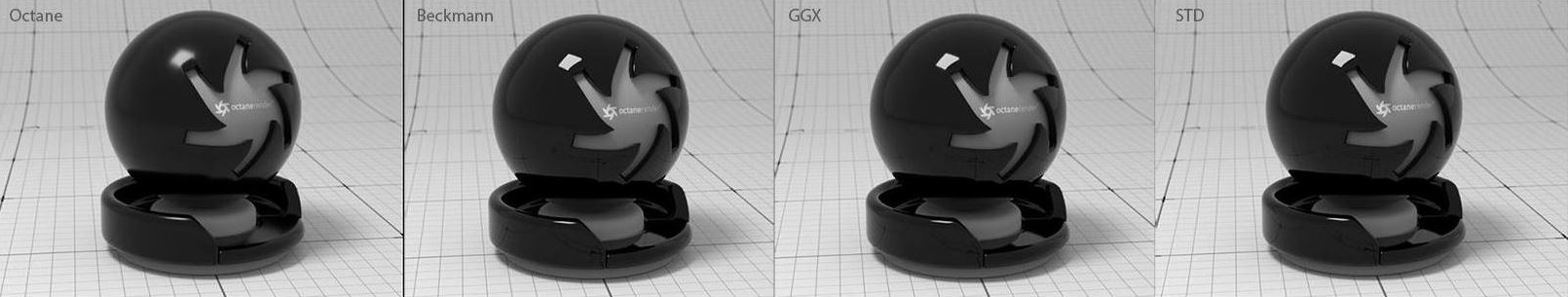
Figure 3: The various BRDF models available for specularity
Roughness - Determines how much the Specular and Transmission characteristics spread across the surface.
Anisotropy - Determines the shape of the Specular and Transmission highlights. A value of -1 creates a horizontal shape, and a value of 1 creates a vertical shape.
Rotation - Controls the Anisotropy shape's rotation.
Spread - Determines the tail spread of the specular BSDF.
Dielectric IOR - This is the IOR that controls the Fresnel effect of the specular reflection or transmission. By default, if the Dielectric 1/IOR parameter is empty, then the dielectric specular uses this IOR parameter instead.
Dielectric 1/IOR - Overrides the Dielectric IOR when a map or value is applied. This parameter is an index of refraction map, where each texel represents 1/IOR.
Metallic Refl. Mode - This attribute, along with the IOR attributes, provide options for controlling the Index of Refraction across a surface.
- Artistic - Uses the Albedo color.
- IOR + Color - Uses the Albedo color and further adjusts the surface brightness by using the IOR.
- RBG IOR - This is the most used mode. It uses the just the three IOR values and ignores the Albedo color altogether.
Metallic IOR - Complex-valued IOR (n-k*i) that controls the Fresnel effect of the specular reflection for Metallic materials. For RGB IOR mode, this serves as the IOR for the red light (650nm).
Metallic IOR (Green) - For RGB IOR mode, this is the IOR for the green light (550nm).
Metallic IOR (Blue) - For RGB IOR mode, this is the IOR for the blue light (450nm).
Allow Caustics - If enabled, the photon tracing kernel will create caustics for light reflecting or transmitting through objects with this material applied.
Coating - Adds a second layer of reflection to the surface.
Coating Roughness - Determines how much the Coating characteristic spreads across the surface.
Coating IOR - Controls the Fresnel effect for the Coating characteristics of the surface.
Coating Bump - Much like a regular Bump map, this creates fine details on the Material’s Coating attribute using a Procedural or Image texture.
Coating Normal - Creates fine details on the surface's coating. However, a Normal map is a special type of Image texture that uses red, green, and blue color values to perturb the surface's normals at render time, thus giving added detail. They can be more accurate than Bump maps, but require specific 3D software to generate.
Film Width - Simulates the look of a thin film of material on the surface. This is useful when you want to create an effect like the rainbow colors that appear on an oil slick's surface. Larger values increase the effect's strength.
Film IOR - Controls the thin film's IOR and its visible colors.
Sheen - Adds a second layer of glossiness to the surface.
Sheen Roughness - Determines how much the Sheen characteristic spreads across the surface.
Sheen Bump - Much like a regular Bump map, this creates fine details in the Material’s Sheen attribute using a Procedural or Image texture.
Sheen Normal - This attribute also creates fine details in the surface's sheen. However, a Normal map is a special type of Image texture that uses red, green, and blue color values to perturb the surface normals at render time, thus giving the appearance of added detail. They can be more accurate than Bump maps, but require specific 3D software to generate.
Dispersion Coefficient - Increasing the Dispersion value increases the amount of coloration and dispersion in the Object’s transmission and in caustics.
Dispersion Mode - Determines how the IOR and dispersion inputs are interpreted.
Medium - OctaneRender for 3DS Max has various types of Mediums:
- Absorption Medium - Produces the appearance of a material that absorbs light while passing through a surface. The resulting color depends on the distance that light travels through the material. For more information, see the Mediums topic in this manual.
- Scattering Medium - Similar to the Absorption medium, but with an additional option for simulating subsurface scattering. Subsurface scattering is the phenomena that gives human skin and similar organic surfaces their characteristic glow under certain lighting conditions. It's a major component for creating the look of realistic skin. For more information, see the Mediums topic in this manual.
- Volume Medium - Adds color and other qualities to a VDB file. VDBs are a generic volume format for creating effects such as smoke, fog, vapor, and similar gaseous objects. VDBs can consist of a single frame, or an animated sequence.
- Random Walk - A newer variant of subsurface scattering that utilizes a stochastic or random process for the scattering of light through an object. This provides the most realistic result when rendering scatter volumes.
- Std Volume Medium - This provides volume medium options with comprehensive controls for adjusting volume, scatter, transparency, emission, and temperature parameters based on imported VBD grid data.
Opacity - Determines what parts of the surface are visible in the render. Dark values indicate transparent areas, and light values determine opaque areas. Values in-between light and dark indicate semi-transparent areas. You can lower the Opacity value to fade the Object's overall visibility, or you can use a Texture map to vary the opacity across the surface. For example, to make a simple polygon plane look like a leaf, connect a black-and-white image of the leaf’s silhouette to the Diffuse shader's Opacity channel.
Fake Shadows - If enabled, light traces through the Material during the shadow calculation, ignoring refraction.
Affect Alpha - Enabling this option causes refraction to affect the Alpha Channel. This parameter has an effect if the Alpha Channel is enabled in the Render settings’ Kernel parameters.
Bump - Creates fine details on the Material’s surface using a Procedural or Image texture. When you connect a Grayscale texture to this parameter, light areas of the texture indicate protruding bumps, and dark areas indicate indentation. You can adjust the Bump map's strength by setting the Power or Gamma values on the Image texture node. These attributes are covered in more detail in the Textures topic of this manual.
Bump Height - Determines the strength of the bump map. A value of 0 provides no bump height and negative values will invert the bump map.
Normal - Also creates fine detail on the surface. A Normal map is a special type of Image texture that uses red, green, and blue color values to perturb the surface normals at render time, giving the appearance of added detail. They can be more accurate than Bump maps, but require specific 3D software to generate.
Displacement - Adjusts the height of the vertices of a surface at render time using a Texture map. Displacement maps differs from Bump or Normal maps in that the geometry is altered by the Texture, as opposed to creating the appearance of detail. Displacement mapping is more complex than using a Bump or Normal map, but the results can be more realistic, in particular along the surface's silhouette. Displacement mapping is covered in more detail under the Texture category.
Smooth - Smooths out the transition between surface normals. If this option is disabled, the edges between the polygons of the surface are sharp, giving the surface a faceted look.
Smooth Shadow Terminator - If enabled, self-intersecting shadows are smoothed according to the polygon's curvature.
Round Edges - Rounds off geometry edges by using a shading effect instead of creating additional geometry. It’s best used for rounded edges that will appear small in the final render. The Fast mode uses the rounding method introduced in OctaneRender® v3. The Accurate mode produces better-looking results, but may be slower. Accurate mode can select the affected edges by using the Concave Only or Convex Only options.
Radius Div - Radius divider, use a high value (10,000) for small scale scenes or geometry.
Rounded Edges Radius - Define the size of the rounded edge by radius. Bevels the surface edges at render time without altering or subdividing the geometry. Using this option enhances object realism by eliminating sharp edges. The value refers to the rounded edge's radius. Higher values produce rounder edges.
Rounded Edges Roundness - Controls the rounded edge's shape. A value of 1 is completely round, while 0 is a chamfer.
Consider Other Objects - Controls how rounded edges are applied to different objects. When enabled, intersections between different objects are rounded. When disabled, only the current object is considered.
R. Edge Samples - Determines the number of rays to use when sampling the neighboring geometry.
Compatibility Mode - The Octane version that the behavior of this node should match. The default is Latest (2022.1.2). The 2022.1.1 compatibility mode will always factor in the edge sharpness instead of just when the material smooth flag is enabled.
Priority - Used to resolve the ambiguity in overlapping surfaces, the surface priority control allows artists to control the order of preference for surfaces. A higher number suggests a higher priority for the surface material, which means it is preferred over a lower priority surface material if a ray enters a higher priority surface and then intersects a lower priority surface while inside the higher priority surface medium.
Emission - Creates a surface that emits light (also known as a Mesh emitter). To use this option, connect the Emission input of the Diffuse material to either a Blackbody or Texture emission node. These nodes are covered in more detail in the Texture topic, and in Mesh Emitters under the Lighting category in this manual.
Shadow Catcher - This converts the material into a shadow catcher. When it is active, the surface is visible in the areas that are in shadow, and all other areas are transparent in the render.
Custom AOV - Writes a mask to the specified custom AOV.
Custom AOV Channel - Determines whether the custom AOV is written to a specific color channel (R, G, or B) or to all the color channels.
Compatibility Mode - The Octane version that the behavior of this node should match. The default is Latest (2023.1). The 2022.1 compatibility mode is the legacy behavior where Bump map strength is active but Bump Map Height is ignored.
Conceal Layer - Hides the Material layer (sub material) of this material from 3ds Max requests. This is to be used temporarily as a work around for the Ornatrix hair viewport display. Note that this layer is still used by Octane but will not be accessible from the Slate editor when Concealed.
Export Octane Material - Opens a dialog window that provides options for exporting the Material to ORBX, the Local DB, or the Live DB.
Convert - Provides options for converting this material to other Octane-specific material types.