Specular Material
The Specular material creates transparent materials like glass and water.
|
|
Specular Material
|

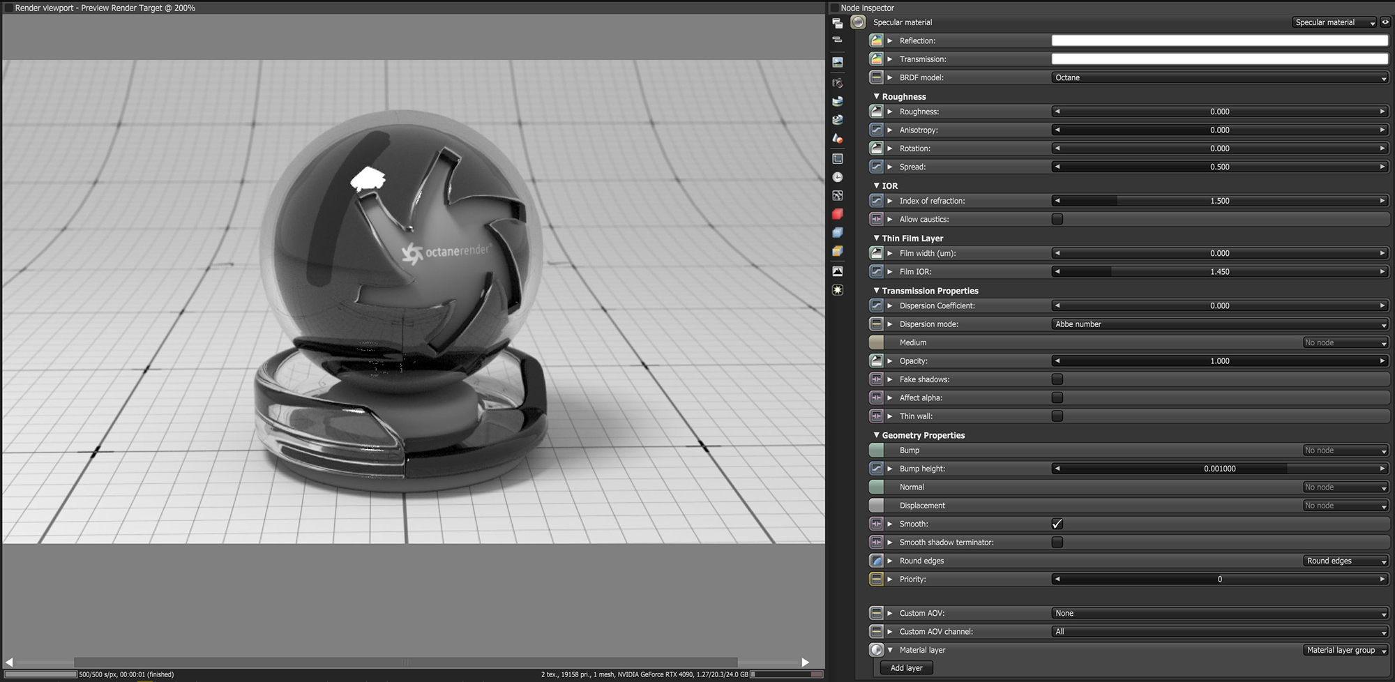
Figure 1: The OctaneRender® Specular material
Specular Material Parameters
Reflection - Determines surface reflection strength. Lower values increase the ability to transmit light through the object volume. Reflection and Index Of Refraction work close together to tune Specular material reflectivity.
Transmission - Controls how light passes through a transparent surface. Transmission and Index Of Refraction work close together to control surface transparency, and Transmission accepts color or texture input. A value of 1 lets light pass through the surface, making it transparent. To create a mirror surface, set this parameter to a black color, and set Index Of Refraction to 0 (Figure 2). To create colored glass, change the color to something other than white or black. Transmission is different than Opacity - Transmission controls transparency, while Opacity controls surface visibility. You can use Transmission to create reflective glass surfaces, and then use Opacity to create a hole in the surface.
BRDF Model- The BRDF (Bidirectional Reflectance Distribution Function) determines the amount of light that a material reflects when light falls on it. For Specular materials, you can choose from five BRDF models. Specific geometric properties (the micro-facet distribution) of the surface affects each BRDF, which describes the surface's microscopic shape (i.e. micro-facet normals) and scales the brightness of the BRDF's reflections.
|
|
BRDF Models
|

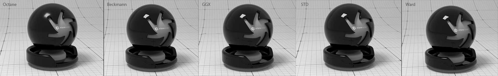
Figure 2: The three BRDF Models applicable to Specular materials
Roughness - Simulates the micro-facets effect in the surface, which blurs surface reflections and surface transparency. To create a translucent plastic look, you make a surface with a white or light-colored Transmission color and a Roughness value greater than 0. This parameter accepts a color value or texture (Procedural or Image) - you'll want to use an alpha image or value. Hue information won't affect Roughness.
Anisotropy - Controls the material's reflectance uniformity. Reflectance changes based on surface orientation, or if the rotation is Anisotropic. If the reflectance is uniform in all directions and doesn't change based on the surface's orientation or rotation, then it is Isotropic. This parameter's default value is 0, which sets the Metallic material as Isotropic. Non-zero values mean the material exhibits Anisotropic reflectance, where -1 is horizontal and 1 is vertical.
|
|
Anisotropic Roughness
|

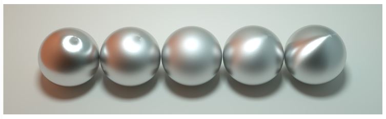
Figure 3: Anisotropic roughness exemplified in materials like brushed metal
Rotation - The rotation of the anisotropic Specular reflection channel.
Spread - Determines the tail spread of the specular BSDF.
Index Of Refraction - Describes the change in the speed of light as it passes through a medium. As light photons move through surfaces like water, they slow down and change direction. This change appears as the object distorting on the other side of the water's surface. A vacuum's Index Of Refraction (IOR) is 1, and water's IOR is 1.33, meaning light travels 1.33 times faster through a vacuum than water. Most transparent surfaces' IOR is accessible on the internet. Knowing a surface's correct IOR is important for replicating a surface's look in OctaneRender®.
Allow Caustics - If enabled, the photon tracing kernel will create caustics for light reflecting or transmitting through the object.
Film Width - Simulates the look of thin film material on a surface, like creating a rainbow color effect that appears on an oil slick's surface. Larger values increase the effect's strength.
Film IOR- Controls the film's IOR by adjusting its visible colors.
Dispersion Coefficient - Increasing this value increases the coloration amount and dispersion in the object's transmission and in caustics.
Dispersion Mode - Determines how the IOR and dispersion inputs are interpreted.
Medium- OctaneRender® has three types of mediums to create translucent surfaces:
- Absorption Medium - Produces the appearance of a material that absorbs light while passing through a surface. The resulting color depends on the distance that light travels through the material.
- Random Walk - A newer variant of subsurface scattering that utilizes a stochastic or random process for the scattering of light through an object. This provides the most realistic result when rendering scatter volumes.
- Scattering Medium - Similar to the Absorption medium, but with an additional option for simulating subsurface scattering. Subsurface scattering is the phenomena that gives human skin and similar organic surfaces their characteristic glow under certain lighting conditions. It's a major component for creating the look of realistic skin.
- Standard Volume - This provides volume medium options with comprehensive controls for adjusting volume, scatter, transparency, emission, and temperature parameters based on imported VBD grid data.
- Volume Medium - Adds color and other qualities to a VDB file. VDBs are a generic volume format for creating effects such as smoke, fog, vapor, and similar gaseous objects. VDBs can consist of a single frame, or an animated sequence. 3D software packages like Houdini generate and export VDBs. You can also download VDB files at http://www.openvdb.org/download/.
Opacity - Determines what surface parts are visible in the render. Dark values indicate transparent areas, and light values indicate opaque areas. Values between light and dark indicate semi-transparent areas. Lowering the Opacity value fades the object's overall visibility, or you can use a Texture map to vary the surface's opacity. For example, if you want to make a simple polygon plane look like a leaf, you connect a black-and-white image of the leaf's silhouette to the Diffuse shader's Opacity channel. When you use an Image texture map, set the Data type to Alpha Image if the image has an Alpha Channel, or Grayscale image for black-and-white images, to load an image for setting transparency. Use the image's Invert checkbox to invert the transparency regions.
Fake Shadows - Activates the Architectural glass option for all meshes sharing that material. When enabled, Specular materials exhibit Architectural glass characteristics with its transparent feature, allowing light to illuminate enclosed spaces or frame an exterior view.
Affect Alpha - This option lets refractions affect the Alpha Channel, as long as you enable the Alpha Channel in the Kernel settings.
Thin wall - When enabled, the geometry becomes very thin, so the ray bounce exits the material immediately, rather than entering the medium.
Bump - Creates fine details on material surfaces using a Procedural or Image texture. When you connect a Grayscale image texture to this parameter, light areas appear as protruding bumps, and dark areas appear as indentations. You can adjust the Bump map strength by setting the Power or Gamma values on the Grayscale image texture node. The Textures topic in this manual covers these attributes in more detail.
Bump Height - Determines the height represented by a normalized value of 1.0 in the bump texture. A vaule of 0 disables the bump map and a negative value will invert the bump map.
Normal - Creates fine details on the surface. A Normal map is a special type of Image texture that uses red, green, and blue color values to perturb the surface normals at render time, giving the appearance of added detail. They can be more accurate than Bump maps, but require specific software, such as ZBrush®, Mudbox®, Substance Designer, xNormal, or others to generate. To load a full-color Normal map, set the Normal channel to the RGB Image data type. Note that Normal maps take precedence over Bump maps, so you cannot use a Normal map and a Bump map at the same time.
Displacement - Adjusts surface vertices' height at render time using a Texture map. Displacement maps differ from Bump or Normal maps by having the texture alter the geometry, as opposed to creating the appearance of detail on the surface. Displacement mapping is more computationally expensive than Bump or Normal mapping, but results are more realistic, especially along the surface silhouette. The Texture Overview topic in this manual has more information.
Smooth - Smooths out the transition between surface normals by blending the edges between polygons together. When disabled, the edges between surface polygons appear sharp, giving the surface a faceted look.
Round Edges - Rounds the edges of geometry by using a shading effect, rather than creating additional geometry. Refer to the Round Edges topic in this manual for more information.
Priority - Used to resolve the ambiguity in overlapping surfaces, the surface priority control allows artists to control the order of preference for surfaces. A higher number suggests a higher priority for the surface material, which means it is preferred over a lower priority surface material if a ray enters a higher priority surface and then intersects a lower priority surface while inside the higher priority surface medium.
Custom AOV - Writes a mask to the specified custom AOV.
Custom AOV Channel - Determines whether the custom AOV is written to a specific color channel (R, G, or B) or to all the color channels.
Material Layer - Adds a Material Layer above the base material. See the Material Layers topic in this manual for more details.