Metallic Material
OctaneRender® Metallic materials are used to create physically-accurate metals (conductors). The Metallic material is clearly distinguished from the Glossy material both in terms of specular and IOR. In the real world, the reflection properties of metals are very high; and it is determined according to the characteristics of the light reflected back, due to way that metals absorb certain wavelengths of light.
When light (electromagnetic radiation) hits the surface of a metal, it gets absorbed by electrons orbiting the metal atoms, and re-emitted as the electrons fall back to a more stable configuration. The electrons are free to move throughout the metal, which explains its high electrical and heat conductance. Certain wavelengths of the rays absorbed by the metal surfaces cause an energy exchange between the electrons. The configuration of these electrons differs according to the type of metal. Copper and gold are the only metals to show a certain color in visible light, which are due to their electron structures. The energy difference between electrons in gold is about 400-492nm and this strong absorption cuts out the blue light from the reflection, creating gold's yellow-orange color. Copper has also similar effect for its electron structure but with lower absorption energy (Blue/Blue-Violet), thus we see an orange color. Silver absorbs more or less all wavelengths of light, so as a result, we see bright white color. The table below shows the colors we see after absorbing certain wavelengths (figure 1).
|
|
Metallic Materials
|


Figure 1: Wavelength and color of common metals
With complex IOR support and the proper values (available from sites such as refractiveindex.info), Octane will correctly present these colors without the need to set them by hand. It is important to properly set the BRDF model (Beckmann, Ward, etc.) to attain realistic metals. These BRDF models use much more advanced Fresnel formulas than the default Octane BRDF and will create a much more realistic metallic render.
|
|
Metallic Material Parameters
|


Figure 2: The OctaneRender Metallic material
Metallic Material Parameters
Diffuse Color - This parameter can accept any color or texture; the color or texture will be visible only when the Specular Map option has a value of less than 1.0.
Specular Color - The specular reflection channel, which determines the metallic color when the Metallic Reflection Mode is set to Artistic.
Edge Tint - The color of the edges of the metal material, only used with Artistic and IOR+Color modes.
Specular Map - Controls the blend between the Diffuse and Specular channels determining how metallic the material will appear.
|
|
Specular Comparisions
|

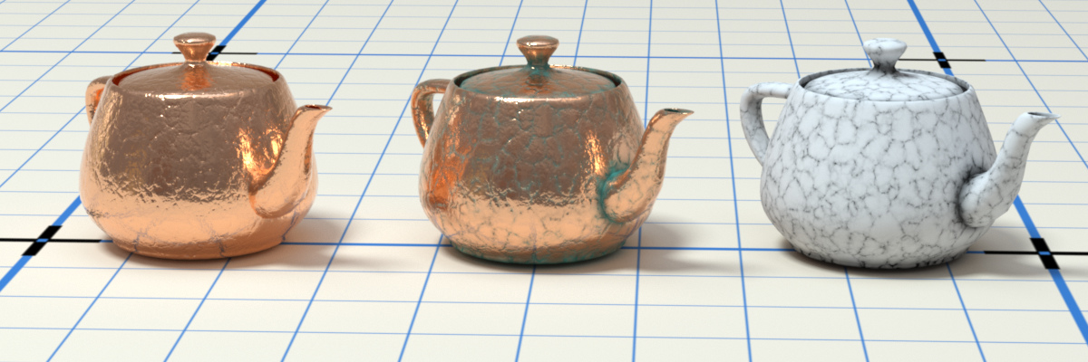
Figure 3: Specular only (left); Specular and Diffuse with Specular map (middle); visualization of the Specular map (right)
BRDF Model - The BRDF (Bidirectional Reflectance Distribution Function) is a function that determines the amount of light reflected from a material when light falls on it. For Metallic materials, there are four applicable BRDF Models to choose from. Each BRDF is affected by a specific geometric property (microfacet distribution) of the surface, which describes the microscopic shape (microfacet normals) of that surface, and it serves as a function to scale the reflections' brightness in the BRDF. More details can be found in the BRDF Models topic.
|
|
BRDF Models
|


Figure 4: The four BRDF Models applicable to Metallic materials
Retro-Reflective - Activates an optical property where the surface reflects incoming light rays directly back to the original light source. Examples are street signs and safety gear.
Roughness
Roughness - Adjusts the Specular reflection channel's roughness.
Anisotropy - Controls the material's reflectance uniformity. If the reflectance changes based on the orientation or the surface rotation, it is Anisotropic. If the reflectance is uniform in all directions and does not change based on the orientation or surface rotation, it is Isotropic. By default, this attribute is 0 and it sets the Metallic material as Isotropic. Non-zero values mean the material exhibits Anisotropic reflectance, where -1 is horizontal and 1 is vertical.
|
|
Anisotropic Roughness
|

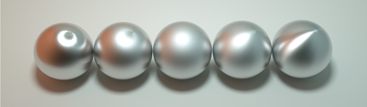
Figure 5: Anisotropic roughness exemplified in materials like brushed metal
Rotation - The rotation of the anisotropic Specular reflection channel.
Spread - Determines the tail spread of the specular BSDF.
IOR
Metallic Reflection Mode - This changes how OctaneRender® calculates reflectivity.
- Artistic - Uses the Specular color. The values entered into the IOR have no impact. It is simple and ideal for non-realistic results.
- IOR + Color - Uses n and k IOR values as Index of Refraction along with the Specular Color.
- RGB IOR - The most accurate IOR mode. Uses the three IOR values; red (650nm), green (550nm), and blue (450 nm) and ignores the Specular color. Refractive Index (n) and Extinction Coefficient (k) are actual index values. For these values go to refractiveindex and enter real IOR values according to material types you selected. Use the numeric field for n on the left and k on the right for each of the IOR (Red but not labled Red), IOR (Green), and IOR (Blue) parameters listed below.
Index Of Refraction - Complex-valued IOR (n-k*i) controlling the specular reflection's Fresnel effect, where n = the refractive index and k = the attenuation or extinction coefficient. For RGB mode, the IOR for red light (650nm).
Index Of Refraction (Green) - For RGB mode, the IOR for green light (550nm).
Index Of Refraction (Blue) - For RGB mode, the IOR for blue light (450nm).
Allow Caustics - If enabled, the photon tracing kernel will create caustics for light reflecting or transmitting through the object.
Sheen Layer
Sheen - The subtle lustre's color on the material's surface.
Sheen BRDF Model - The BRDF (Bidirectional Reflectance Distribution Function) is a function that determines the amount of light reflected from a material when light falls on it. The Sheen option creates an overall sheen across the surface and the Fuzz option create a more subtle micro-fiber effect (like peach fuzz or fine hair).
Sheen Roughness - The Roughness channel for the sheen that is present on Metallic and Glossy materials.
Thin Film Layer
Film Width - Simulates the look of a thin film of material on the surface. This is useful when you want to create an effect such as the rainbow colors that appear on an oil slick surface. Larger values increase the effect's strength.
Film IOR - Controls the thin film's IOR by adjusting its visible colors.
Transmission Properties
Opacity - Controls the Toon material's transparency with a Grayscale texture.
Geometry Properties
Bump - Simulates a relief using a Grayscale texture interpreted as a Height map.
Bump Height - Determines the height represented by a normalized value of 1.0 in the bump texture. A vaule of 0 disables the bump map and a negative value will invert the bump map.
Normal - Distorts normals based on an RGB image.
Displacement - Adjusts the height of a surface's vertices at render time using a texture map. Displacement maps differ from Bump or Normal maps in that the geometry is altered by the texture, as opposed to just creating the appearance of detail. Displacement mapping is more complex than using a Bump or Normal map, but the results are more realistic, especially along a surface's silhouette. Displacement works with the texture nodes, and the displaced mesh must have UV Texture coordinates. Procedural texture nodes, such as Turbulence or Marble, need to be converted using the Baking Texture node. For more information, see the Displacement topic in this manual.
Smooth - Enables or disables normal interpolation. If normal interpolation is disabled, triangle meshes appear faceted.
Smooth Shadow Terminator - If enabled, self-intersecting shadows are smoothed according to the polygon's curvature.
Round Edges - Rounds the geometry edges by using a shading effect rather than creating additional geometry. For more information, see the Round Edges topic in this manual.
Priority - Used to resolve the ambiguity in overlapping surfaces, the surface priority control allows artists to control the order of preference for surfaces. A higher number suggests a higher priority for the surface material, which means it is preferred over a lower priority surface material if a ray enters a higher priority surface and then intersects a lower priority surface while inside the higher priority surface medium.
Custom AOV - Writes a mask to the specified custom AOV.
Custom AOV Channel - Determines whether the custom AOV is written to a specific color channel (R, G, or B) or to all the color channels.
Material Layer - Adds a Material layer above the base material. See the Material Layers topic in this manual for more details.