Imager Settings
The camera Imager settings provide useful parameters for post-rendering adjustments. The Denoiser parameters can also be found in these settings. To adjust the camera imager settings, select the Imager node in the Graph Editor, or select the Current Imager icon in the Node Inspector (Figure 1).
|
|
Node Inspector toolbar
|

Figure 1: The Camera Imager button on the Node Inspector toolbar
Camera Imager Parameters
Exposure - Controls the scene exposure. Smaller values create a dark scene, while higher values create a bright scene. Exposure has no effect on any of the render layer passes.
Hot Pixel Removal - Removes bright pixels (fireflies) during the rendering process. While many of the pixels can disappear if the render progresses, Hot Pixel Removal removes bright pixels at a much lower sample-per-pixel.
Vignetting - Adjusting this parameter increases the amount of darkening in the corners of the render. Used sparingly, it can increase the render's realism. Vignetting is not applied to any of the beauty passes except the main pass.
White Point - Specifies the color for adjusting the tint to produce and simulate the relative temperature cast throughout the image by different light sources. The white point is white by default, acting as a white balance to achieve the most accurate colors possible.
Saturation - Adjusts the amount of color saturation in the render.
Disable Partial Alpha - Makes pixels that are semi-transparent (Alpha > 0) into fully opaque pixels.
Dithering - Adds random noise, which removes banding in very clean images.
Minimum Display Samples - The minimum amount of samples calculated before the image displays. This feature can reduce noise when navigating, and is useful for real-time walkthroughs. When using multiple GPUs, it is recommend setting this value as a multiple of the number of available GPUs for rendering. If rendering with four GPUs, set this value to 4 or 8.
Maximum Image Interval - Maximum interval between image operations in seconds.
OCIO
OCIO View - The OCIO view to use when displaying in the render viewport. See the Color Management section for more information.
OCIO Look - The OCIO look to apply when displaying in the render viewport, if using an OCIO view.
Force Tone Mapping - Before applying any OCIO looks, this toggles whether to apply OctaneRender's built-in tone mapping when using an OCIO view.
Tone Mapping
ACES Tone Mapping - Uses the ACES 1.2 RRT+sRGB. If this option is enabled, all other tone mapping settings will be ignored.
Highlight Compression - Reduces burned out highlights by compressing them and reducing their contrast.
Clip To White - When the sun is too bright, it can create multicolored reflections. Increasing this value changes the colors to white. This is also applicable to all sources of light. Saturated parts of the render can be pushed towards pure white with this option. This helps avoid large patches of fully saturated colors caused by over-bright light sources such as very bright colored emitters or reflected sunlight off colored surfaces.
Order - This defines the order in which the Response Curve, Gamma, and Custom LUT are applied on the scene. 3D LUTs are defined for sRGB input values (Custom LUTs should be applied last), but there might be 3D look-up tables for linear input data, in which case the Custom LUT should be applied first.
Response Curve - Selects measured camera response curves. Octane also has response curves that reproduces the rendering neutrally on a normal display. The sRGB, Gamma 2.2, and Gamma 1.8 options are applicable for most displays that use sRGB or apply a gamma of 2.2 or 1.8.
|
NOTE The most common response curve is sRGB, which is the camera Imager node's default setting. Since this option did not exist in earlier versions of OctaneRender®, any scene with an sRGB response curve in the Imager settings reverts to Linear/Off in older versions. |
For examples of all the camera responses, see the Appendix topic in this manual on Camera Response Curve.
Neutral Response - If enabled, the camera response curve does not tint the render result. In Figure 3, the left image is the material ball rendered with no response curve and Gamma set to 2.2. The center image uses the Agfacolor HDC 200 curve and a Gamma of 1. The right image shows the same curve with Neutral Response enabled.
|
|
Neutral Response Curve
|
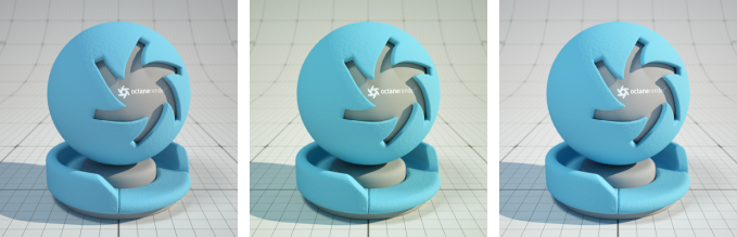
Figure 3: Adjusting the Neutral Response curve
Gamma - Adjusts the render gamma and controls the image's overall brightness. Images that are not properly corrected can look bleached out or too dark. Varying the amount of Gamma correction changes the brightness and the ratios of red to green to blue.
Custom LUT - Specify any standard or user-defined 3D Lookup Table (.cube file) for OctaneRender® to map one color space to another. If this attribute is set, the custom LUT is applied in the order specified through the Order attribute.
Denoiser & Real-Time Denoiser
This section provides options for the denoising capabilities of Octane, rendering noise-free images with fewer kernel samples. For more information, see the Denoiser topic in this manual.
Upsampler
This section provides options for the upsampling capabilities of Octane, performing faster renders at a lower resolution, then upscaling to the final resolution. For more information, see the AI Up-Sampler topic in this manual.