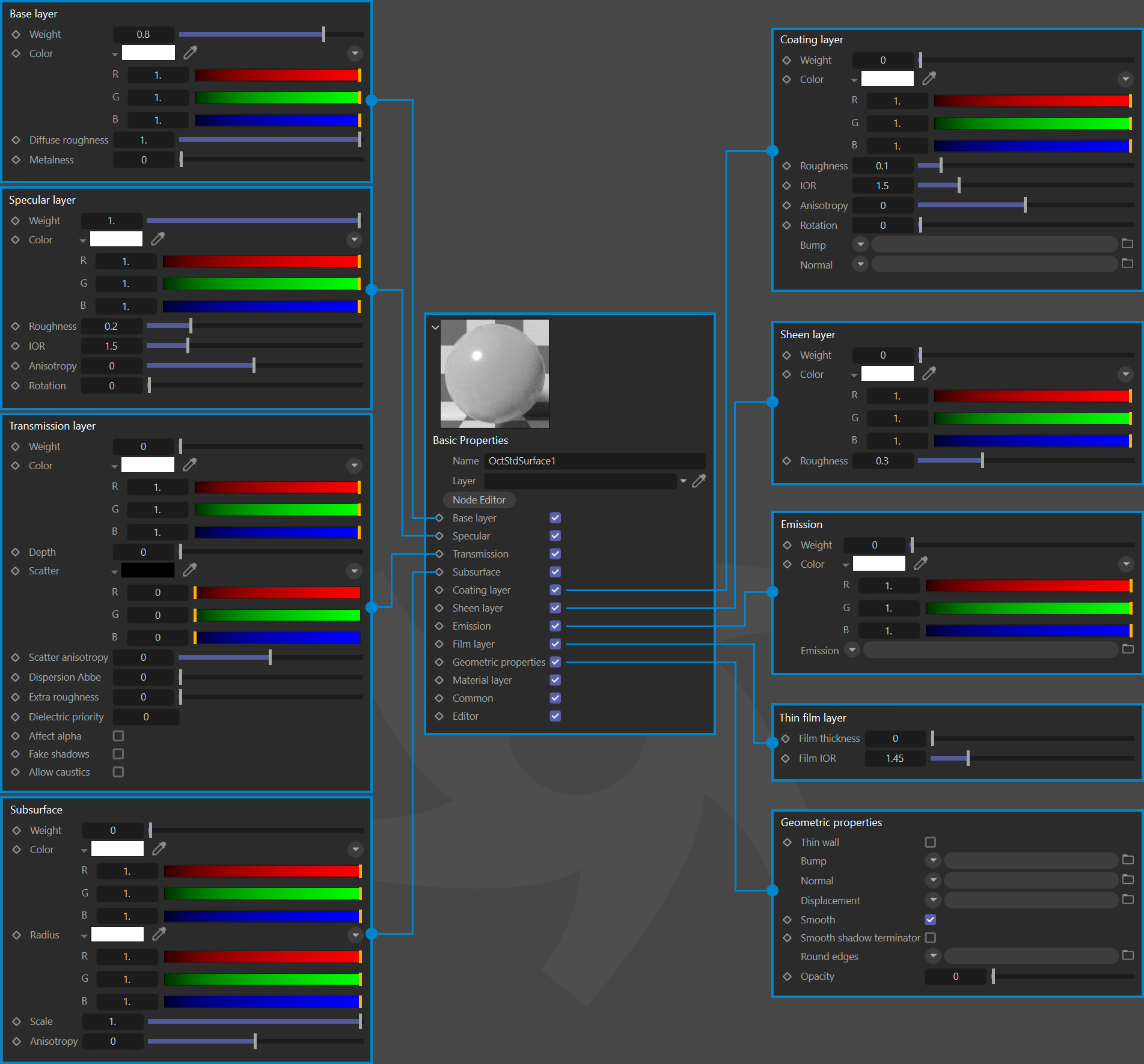
Standard Surface
Octane has implemented a new Standard Surface Material node conforming to the Autodesk Standard Surface specification (originally developed for the Arnold render engine.) Much like Octane’s Universal Material, the Standard Surface material is an über surface shader with multiple layers of BSDF(s). The main differences between the two are the Layered mixture model specified by the Autodesk Standard Surface specification, where the layers of BSDF(s) are arranged differently to the Universal Material, and the far more sophisticated metallic shading options found in the Octane Universal Material.
Layered Mixture Model
Layering accounts for different materials stacked upon each other and mixing determines how, or if, these layers are blended together. The layer stack has either an opaque to transparent bottom, with semi-transparent, dielectric layers built up from the bottom to the top, the mixture of which determined by a variety of factors. The absorption of each layer is determined by the characteristics of each layer in the stack (which can represent wood; metal; glass; skin; etc.).The boundary of each layer reflects or absorbs based upon what the layer represents. Light is reflected between layers; any light that is not reflected is transmitted down towards the next layer. with absorption inside its corresponding medium (according to the specification, as defined here). As each layer mix is linear, the mix operation maintains energy conservation.
The Standard Surface material is a BSDF material, for bidirectional scattering distribution function, describing the light scattering properties of a given surface at a given point and direction (considering the emission component and a subsurface scattering distribution.) The material will collect the light scattering that occurs inside the entire material, which results in the topmost scattering of the material itself.
Due to different implementations of individual material layer closures, the Standard Surface material node in Octane can render slightly different to that in Arnold, but the behavior of inputs are matched as closely as possible.
|
|
Standard Surface
|
Standard Surface Components
In addition to the Layered mixture model, we have updated the implementation of individual layers to support the Standard Surface specification:
- Oren Nayar BRDF
- Textured anisotropy
- Specular boundary SSS layer
- Diffuse boundary SSS layer
- Reparameterization of material inputs
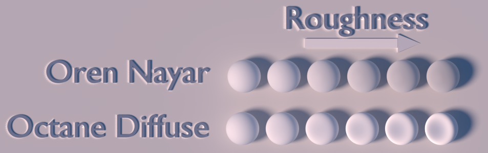
Oren Nayar diffuse BRDF
Octane 2022.1 has implemented a new diffuse BRDF as suggested by the Standard Surface specification for the base diffuse layer, which allows for varying diffuse roughness like the default Octane diffuse model, see below image for the effect of changing roughness to the Oren Nayar diffuse model.
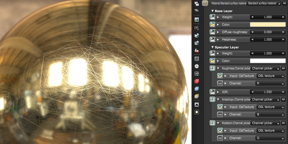
Textured anisotropy for specular and coating layer
The anisotropic reflection channel can now be textured, allowing you to specify the spatially varying anisotropy in either tangent/bi-tangent direction in texture space, while the rotation still remains, allowing you to rotate the anisotropic reflection simultaneously.
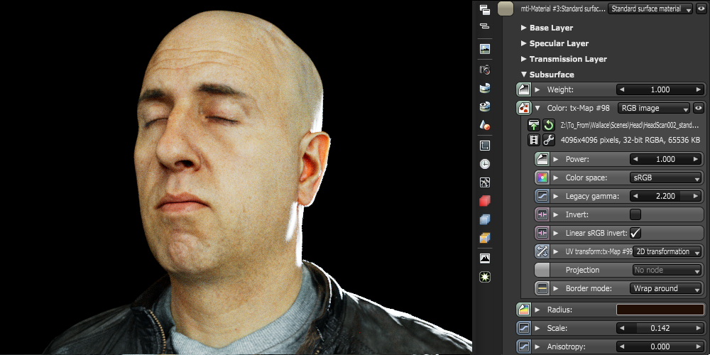
Reparameterization of dispersion Abbe, thin film thickness, and subsurface scattering layer
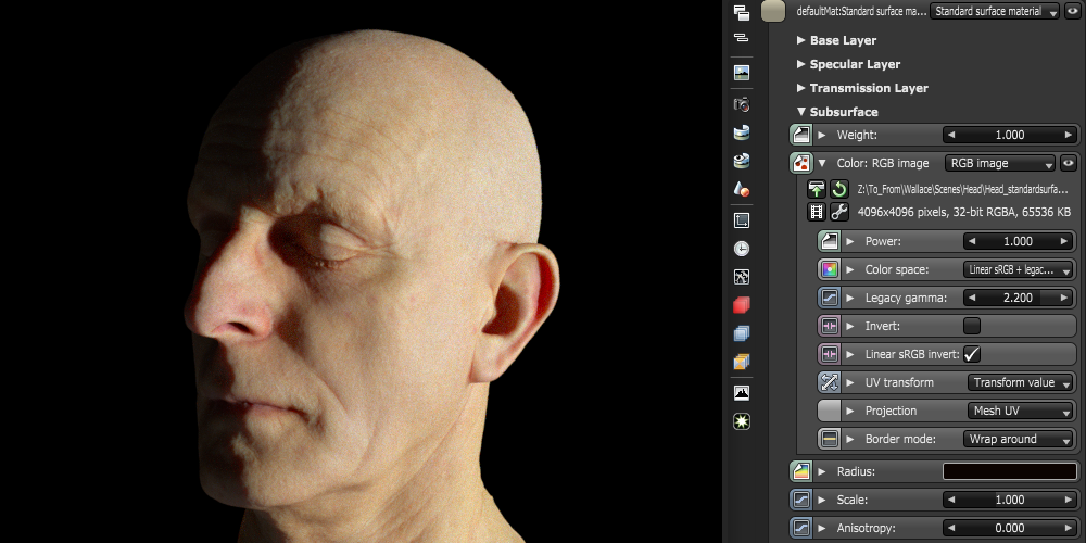
Several parameters are now re-scaled to fit the Standard surface specification. Dispersion is now specified using the dispersion Abbe number and is unbounded, while thin film thickness is now specified in nanometers. Subsurface scattering is also defined as separate layers as in standard surface, with the transmission layer allowing you to specify medium absorption and scattering behavior for the material with specular fresnel boundaries. On the other hand, the subsurface layer allows you to specify medium absorption and scattering behavior for the material with a diffuse boundary.
Below are some examples of the simplified approach rendering with a single subsurface scattering layer using a single colored texture:
Base Layer
|
|
Base Layer
|

Base Weight — Contribution of the base layer.
Base Color — Color of the base layer.
Diffuse Roughness — Diffuse roughness to allow simulation of very rough surfaces like sand or clay.
Metalness — The metallic-ness of the material, blends between dielectric and metallic.
Specular Layer
|
|
sPECULAR Layer
|
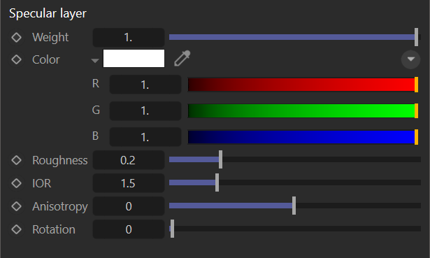
Weight — Contribution of the Specular layer.
Color — The Specular reflection channel determines the color of the glossy reflection for dielectric materials. If the Index of Refraction (IOR) is set to a value greater than 0, then the brightness of this color is adjusted so it matches the Fresnel equations.
Roughness — Roughness of the specular reflection and transmission channel.
IOR — Index of refraction control the Fresnel effect of the Specular reflection or transmission.
Anisotropy — The anisotropy of the specular and transmissive material, -1 is horizontal and 1 is vertical. 0.0 is isotropic.
Rotation — Rotation of the anisotropic specular reflection and transmission channel.
Transmission Layer
|
|
TRANSMISSION Layer
|
Weight — Transmission weight controlling the contribution of light passing the surface of the material (via refraction).
Color — Transmission color tint for refraction.
Depth — The distance travelled inside the material by white light before its color become transmission color by beer's law, if it is zero then transmission color is applied constantly as it crosses boundary.
Scatter — Scattering coefficient of the interior medium.
Scatter Anisotropy — The anisotropy of the Henyey-Greenstein phase function of the interior medium ranging between -1 and 1.
Dispersion Abbe — The dispersion Abbe number, describing how much the index of refraction varies across wavelengths.
Extra Roughness — Additional (positive or negative) roughness on top of specular layer roughness.
Dielectric Priority — The material priority for this surface material.
Affect Alpha — Enable to have refractions affect the alpha channel.
Fake Shadows — If enabled, light will be traced directly through the material during the shadow calculation, ignoring refraction.
Allow Caustics — If enabled, the photon tracing kernel will create caustics for light reflecting or transmitting through this object.
Subsurface Layer
|
|
SUBSURFACE Layer
|
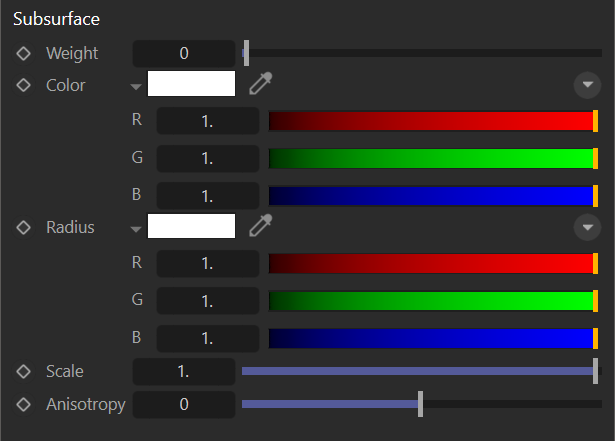
Weight — Contribution of diffuse transmission.
Color — Color used for subsurface scattering.
Radius — Subsurface radii (i.e. mean free paths) of the red, green, and blue channel.
Scale — Scalar scale for subsurface radius.
Anisotropy — Anisotropy of the subsurface medium phase function, ranging between -1 and 1.
Coating Layer
|
|
COATING Layer
|

Weight — Reflection weight of the coating layer (reflection color is fixed to white).
Color — Tint color for the light coming from all layers below.
Roughness — Roughness of the coating layer.
IOR — Roughness of the coating layer.
Anisotropy — Roughness of the coating layer.
Rotation — Rotation of the anisotropic coating reflection.
Bump — The bump map for coating layer:
1. When not specified, the coating layer uses default shading normal.
2. When specified, it applies bumped/normal mapped surface to the coating layer.
Normal — The normal map for coating layer:
1. When not specified, the coating layer uses default shading normal.
2. When specified, it applies bumped/normal mapped surface to the coating layer.
Sheen Layer
|
|
SHEEN Layer
|
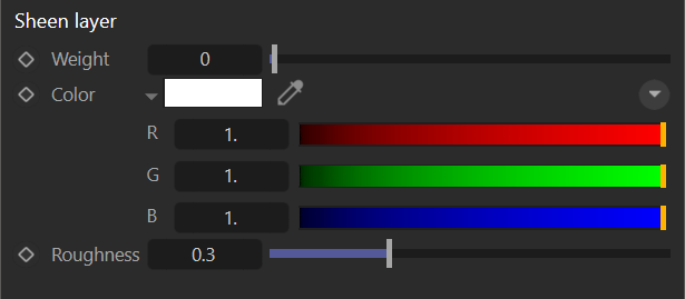
Weight — The contribution of sheen layer.
Color — The sheen color of the material.
Roughness — Roughness of the sheen channel.
Emission Layer
|
|
eMISSION Layer
|
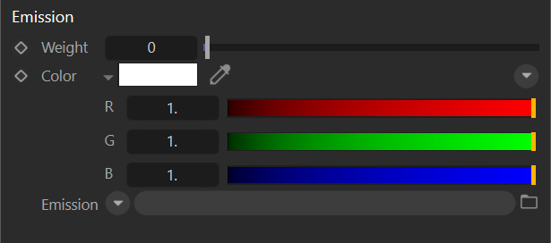
Weight — The scale multiplier for emission.
Color — The emission color.
Emission — Octane emission channel.
Thin Film Layer
|
|
tHIN fILM Layer
|
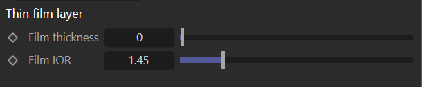
Film Thickness — Thickness of the film coating in nanometers.
Film IOR — Index of refraction of the film coating.
Geometric Properties
|
|
gEOMETRIC pROPERTIES Layer
|
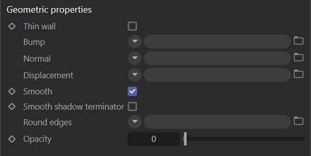
Thin Wall — The geometry the material attached is a one sided planar, so the ray bounce exits the material immediately rather than entering the medium.
Bump — Bump channel to simulate a relief using a grayscale texture interpreted as height map.
Normal — Normal channel to distort normals using an RGB image.
Displacement — Displacement channel to create highly detailed geometry with a low memory footprint.
Smooth — If disabled normal interpolation will be disabled and triangle meshes will appear "facetted".
Smooth Shadow Terminator — If enabled self-intersecting shadow terminator for low polygon is smoothed according to the polygon's curvature.
Round Edges — Smooth sharp edges during render time.
Opacity — Opacity channel controlling the transparency of the material via grayscale texture.
Material Layer
|
|
mATERIAL Layer
|
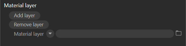
Material Layer — Material layer above this base material.