Dirt
The Dirt generator node is one of the more versatile nodes in OctaneRender® when it comes to creating realistic materials. The Dirt generator will create a grayscale value map that considers the topology of the surface to which it is applied, depending on the settings described in the following section. The generator will create the map by determining the angle between neighboring polygons, modified by your input.
The universal dirt system was first introduced in OctaneRender 2020.1 and replaces and improves upon the previous dirt system, by offering more control and a better look overall. The previous iteration used a uniform cosine sampling for tracing out the rays from the material surface, which resembled unbiased ambient occlusion. The universal dirt system uses an inverted cone-based method to control the distribution of the dirt rays, which offers a much better look than the original dirt node. This method allows you to control the way that dirt rays are sampled and distributed within the inverted cone (the apex of the cone being the point on the surface to be shaded), the results of which can be further modulated with texture input and the controls described in the following section to really finesse the results for a far more realistic look.
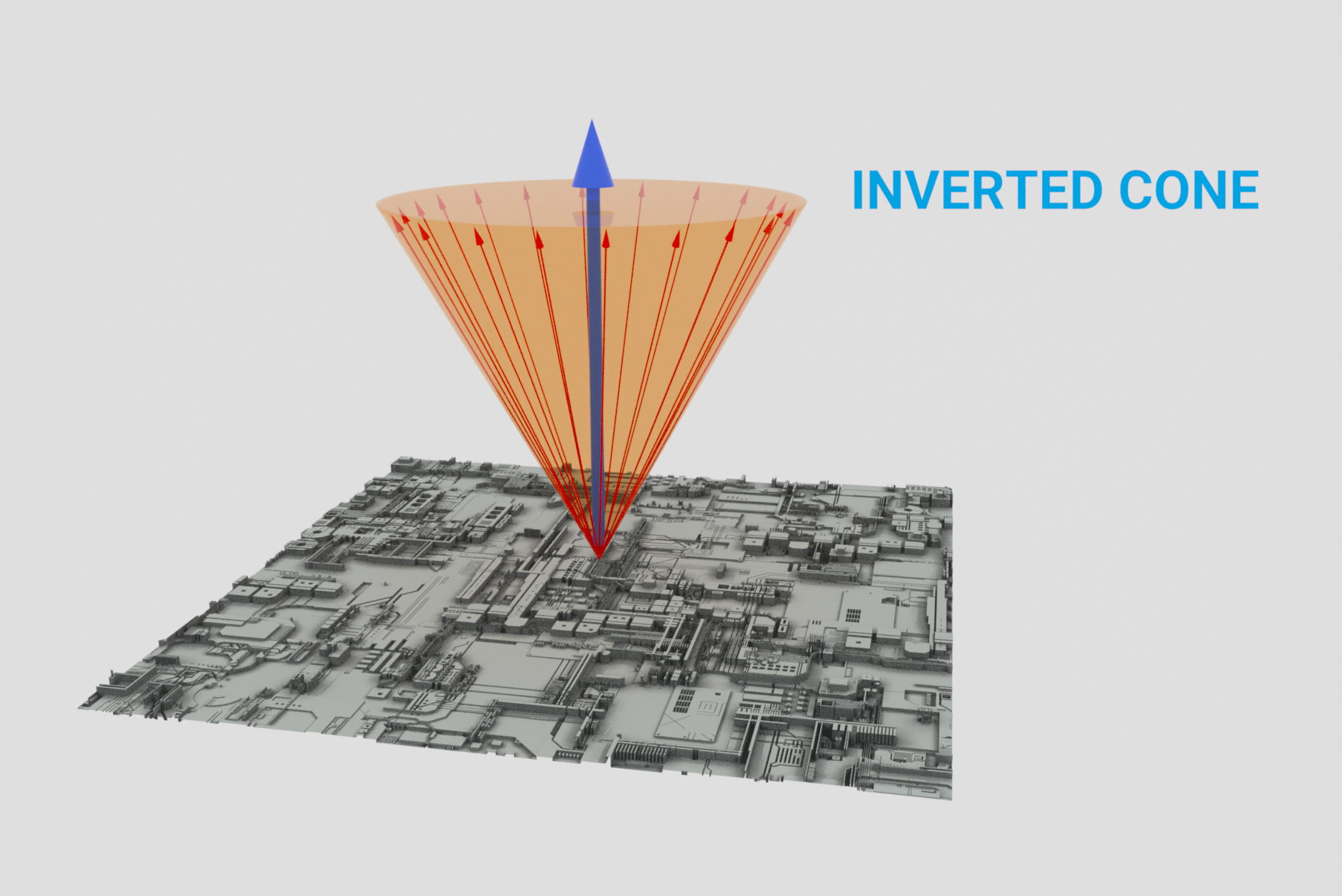
Inverted cone sampling, with apex of the cone as the origin for sampling rays. In this image, sampling rays are at 100% distribution.
The discussions that follow will explore the new components of the universal dirt system. You may wish to keep in mind the inverted cone concept in order to help you better understand some of the values presented.
|
IMPORTANT Vertex Displacement displaces vertices during the geometry compilation phase, before the render even starts. Dirt and curvature are only calculated during render time. Neither dirt nor curvature can be used to influence vertex displacement generation, which has already been completed before dirt and curvature are considered. |
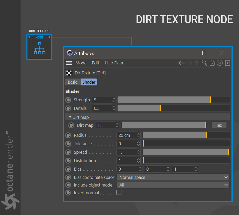
Dirt Generator Settings
Strength
This setting controls the intensity of the dirt effect across the surface of the geometry.
Details
This setting controls the intensity of details revealed in the dirt texture. You can better observe this effect if your object in the scene has detailed and sharp edges. Increasing the value of this slider will cause the dirt effect to spread away from corners, while lower values keep the effect tighter.
Dirt Map
Any texture input (image texture, procedural, etc.) can be used to modulate the intensity and the spread of the dirt effect for a given distance from a surface point. Using a dirt map will help to break up the effect visually, allowing for a more natural, yet art-directed appearance.
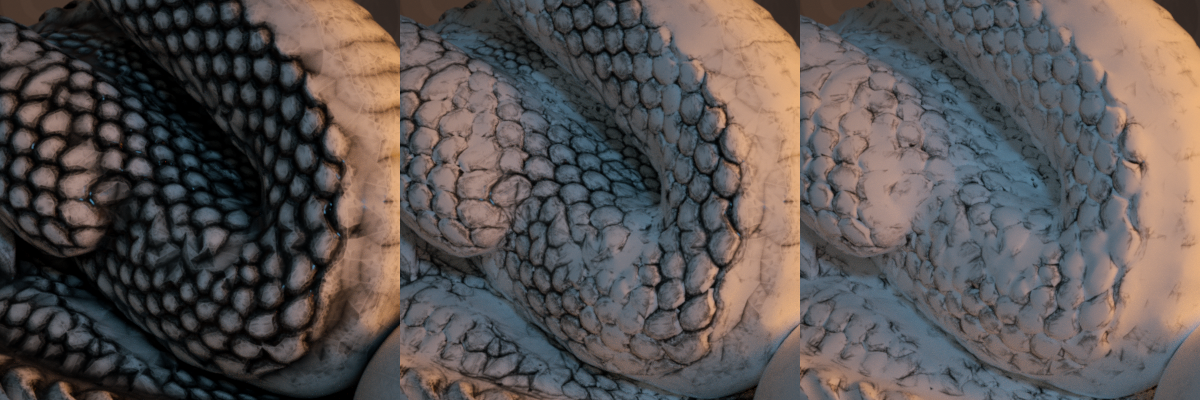
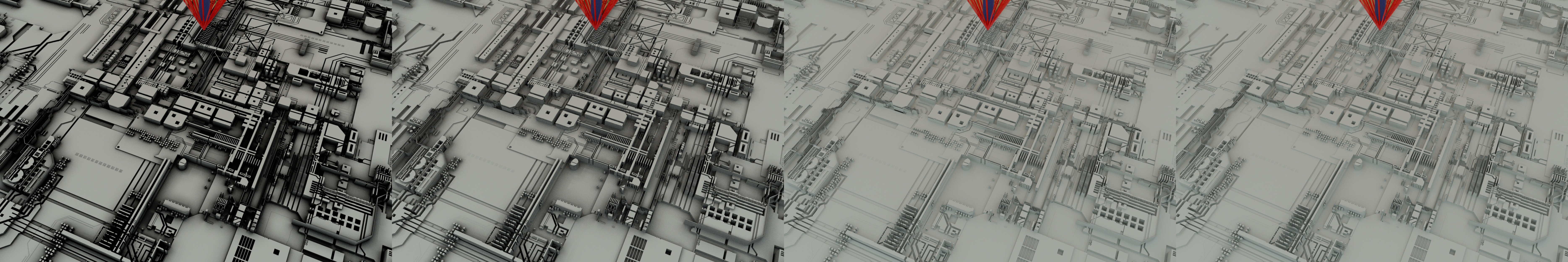
In the illustration above, the left image has just the dirt generator alone, set to a strength of 5, details at 10 and radius at 20. The center image uses a marble procedural in the direct map texture input, and the right image a ridged fractal in the texture input. The dirt map settings are the same for all three images, with only the procedural generators modulating the dirt result.
Radius
This setting controls the spread of the dirt across the surface from the recessed parts of the model outward towards the more exposed parts of the model. The more you increase the radius setting, the more pronounced the dirt effect will be across your geometry.
Tolerance
At some point, you will begin to see the outlines of polygons give away the effect of the dirt generator, and that is where the tolerance attribute becomes an ally. This setting can be used to reduce the appearance of those polygonal artifacts and let you dial in the look you want.
Spread
The spread parameter controls the visibility of the dirt effect across the surface. Lower values produce a less noticeable effect, whereas higher values will cause the effect to become more pronounced.
The illustration above shows the spread parameter in action, going from a value of 1.0 on the left, through 0.25, to 0.0, and finally, no dirt effect at all. The lower the spread is, the less pronounced the effect, since the dirt ray is always sampled in one direction.
Distribution
The distribution value refers to the way that the dirt rays are distributed within the inverted cone (again, the apex of the cone being the point on the surface to be shaded). The default distribution is even (1), but you can weight that distribution using the distribution value (>1-100). The larger the distribution value, the more dirt rays will favor the edges of the cone as opposed to the center of the cone (the normal). The width of the cone itself is controlled by the spread value, discussed above.
In other words, values closer to 1 will produce a less defined dirt effect, which is spread out farther away from the edges. Values closer to 100 will tighten up the spread of the effect and darken the effect as well.
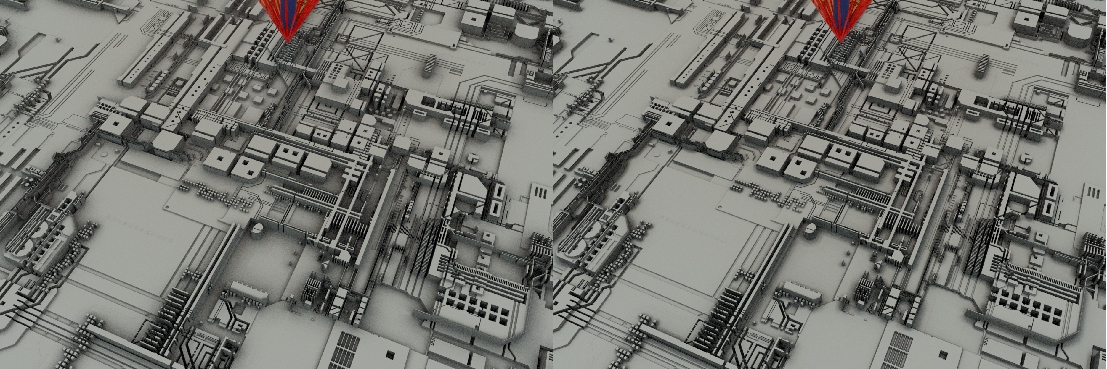
In the illustration above, the left image is with default 1.0 distribution (evenly distributed dirt rays), while the right image is with 100.0 distribution (concentrated in the normal + bias direction).
Bias
You can determine the direction of the inverted cone, and thus the dirt effect, with the bias control. This option allows for a directional input on three separate axes (X, Y and Z -- a vector, in other words) to control the direction in which the base of the cone is pointing, as rotating from the apex (again, the point on the surface to be shaded). The bias works in concert with the distribution parameter, as noted previously. The Bias setting may not be as noticeable in many situations (camera angle, topology, and so on.)
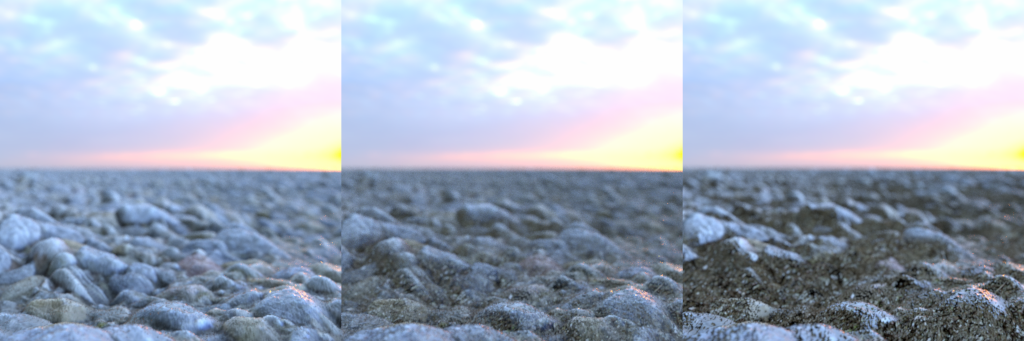
The image above shows three different bias conditions. The image on the left has no dirt generator applied. The middle image shows unbiased, even dirt and the image on the right shows a biased dirt result.
Bias Coordinate Space
The bias coordinate space allows you to determine how the bias direction vector will be calculated spatially and will affect the way the dirt effect is ultimately applied to the surface. You can choose between the following:
- World space: Octane will interpret the input bias controlling the cone orientation as a vector in world space, with the origin being 0,0,0.
- Normal space: the bias vector controlling cone orientation will occur in normal space, from the shading point.
- Object space: the bias vector for cone orientation will be calculated in object space, from the center of the object as defined by the origin point set in Cinema 4D, which can be changed by you.
Include Object Mode
This mode will determine what objects will be considered when calculating the dirt effect for the material. The options are:
- All: All objects will contribute to the dirt effect for the surface if they fall within the sampling parameters.
- Self: Only the object to which the material is applied will contribute to the dirt effect. No other objects will contribute.
- Others: Only other objects will contribute to the dirt effect. The object receiving the effect will NOT contribute.
Invert Normal
This is a toggle which reverses the effect of the Dirt texture based on the normal direction of the surface.
Dirt Performance
Depending upon several factors, the Dirt node may have a noticeable impact on render times. Here are some points to consider, as well as what you can do to address them:
- Dirt is a live node; calculation depends on the complexity of the geometry to which it is applied.
- Animated geometry will update the results of the Dirt node for every frame; if you do not want the effect to change frame-to-frame, then connect the Dirt node to a Bake Texture node into a diffuse material and use a baking camera. Once you have that result, you can replace the Dirt node with the baked texture. This has the added benefit of speeding up your scene.
- Limit one Dirt node per material and you will get better performance.
Using the Dirt Generator: Simple and Advanced
The universal dirt system is one of the more versatile generators that you have in your arsenal. You can use dirt directly as an input in your material shading channels, as a mask blending multiple materials together, as a mask blending textures together, and so on. The list is effectively limitless, enhanced by the upgraded universal dirt system's ability to modulate dirt with image textures, procedural shaders and the like. That said, you can keep things as simple as you need, or as advanced as you wish. Below we have provided two examples, one simple and one advanced.
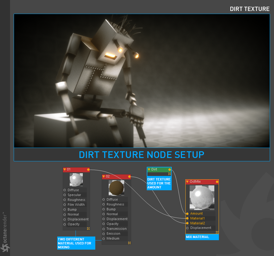
Simple
Open the Node editor and prepare the setup as you see in the picture below. Create two different materials and one Octane mix material. Connect two materials into the mix material slots respectively. For the amount channel create a dirt node and change the settings.
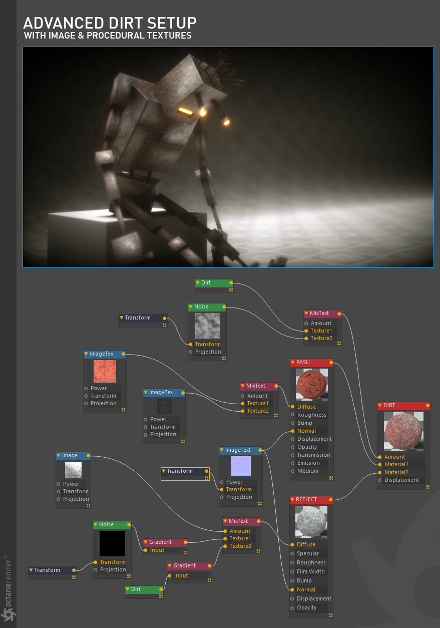
Advanced
While more complex than the previous example, if you look carefully at the image, you will see that "Dirt" is used in 2 places. One dirt node is being used as a mask between two textures in the MixText node, and the other dirt node is being used as an input to a gradient node, which is feeding into another MixText node that will ultimately be used to drive the diffuse channel in a material intended to control the reflectivity of the first material. It reads more complicated than what it actually is.
Getting More Information
There are many sources of information available online, and often for free, that will discuss how to use the dirt system in Octane. In some cases, these resources will be referring to the original dirt system, but the same rules still apply. Just know that you now have more features, and the results will look even better than before. That basic principles of use for the first system have not changed.