Universal Material
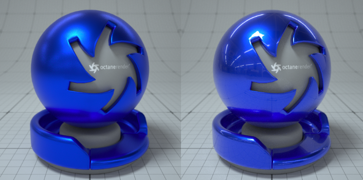
The Universal material puts Substance maps and PBR outputs into OctaneRender®. Substance Painter and other engines map well to this material. Universal materials blend between dielectric and metallic with a Metallic parameter value from 0 - 1. Compared to other materials, the Universal material is equivalent to the Metallic material when its Metallic parameter is set to 1.0, and it is similar to the Glossy material when its Metallic parameter is set to 0.0(figure 1).
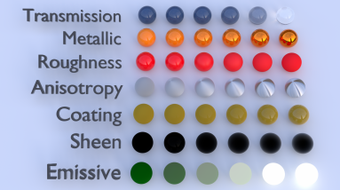
The Universal material is designed to follow after the workflow in the PBR model, since the Metallic material falls short of the metallic and roughness maps that are often derived from Substance Painter and other tools. It handles dielectric material (Diffuse and Glossy BRDF) and also Metallic material (Glossy BRDF) with assumed IOR or custom IOR for both dielectric and metallic surfaces (figure 2). Material IOR in the base layer of Universal materials is also not limited to scalar values, and this can be controlled procedurally with texture-type nodes and OSL shaders connected to a new IOR texture input pin.
|
|
Metallic vs Glossy
|
Figure 1: Example of Metallic parameter set to 1 and 0
|
|
Material Types
|
Figure 2: Creating basic and complex materials with Universal materials
You can also import the BaseColor maps, Height maps, Normal maps, Occlusion maps, and other texture maps for a scene derived from major 3D painting software into OctaneRender®, and then re-link these texture maps to the corresponding Universal material node pins (figure 3). The Universal material node blends the Glossy and Metallic materials, depending on the Metallic input settings. You can then adjust each texture's settings in greater detail. For example, you can place real-world IOR values of Metallic objects as part of the Universal material's Red, Green, and Blue IOR metallic input channels (figure 4).
|
|
Relinking Texture Maps
|
Figure 3: Relinking texture maps to the corresponding Universal material pins
|
|
IOR Values
|
Figure 4: Placing real-world IOR values of Metallic objects as part of the IOR metallic input channels (Red, Green and Blue)
Universal Material Parameters
Transmission Layer
Transmission - Controls the light passing the surface of the material (via refraction).
Transmission Type - Determines how light refracts.
- Specular - Behaves the same as transmission of the specular material, taking IOR and roughness into account.
- Diffuse - Behaves the same as transmission of the diffuse material, not taking IOR into account and roughness has the same meaning as the in the diffuse material. If additional layers are used, the layer ordering is dependent on the side the incident rays comes from.
- Thin Wall - Behaves the same as mode Specular but with no refraction and no roughness for transmission.
- Thin Wall (Diffuse) - Behaves the same as mode Diffuse with the exception that the layer ordering is independent of which side the incident ray comes from. Could be used with a coating layer for foliages and leaves.
Base Layer
Albedo - The material's base color.
Diffuse BRDF Model - Provides three models for diffuse light reflectance. Lambertian reflects light equally in all directions and does not support roughness. The Octane option creates a sheen effect much like velvet. And, the Oren-Nayar option behaves more like clay.
Metallic - The material's metallic appearance. Blends between dielectric and metallic material.
Metallic Edge Tint - The color of the edges of the metal material, only used with Artistic and IOR+Color modes.
Specular Layer
Specular - Determines the color of glossy reflections. If the Index Of Reflection is set to a value less than 0, the color's Brightness adjusts to match with the Fresnel equations.
BSDF Model - Determines the amount of light that a material reflects when light falls on it. For Specular materials, you can choose from five BSDF models. Specific geometric properties (the micro-facet distribution) of the surface affects each BSDF, which describes the surface's microscopic shape (i.e. micro-facet normals) and scales the brightness of the BSDF's reflections.
Roughness
Roughness - Roughness values for the Specular reflection and Transmission channel.
Anisotropy - Anisotropy values for the Specular and Transmission materials. -1 is horizontal, while 1 is vertical. A value of 0 is Isotropic.
Rotation - Rotation values for the Anisotropic Specular reflection and Transmission channel.
Spread - Determines the tail spread of the specular BSDF.
IOR
Dielectric IOR - The Index Of Refraction controlling the Specular reflection's or Transmission's Fresnel effect. By default, if Dielectric 1/IOR Map is empty, then the dielectric specular layer uses this IOR.
Dielectric 1/IOR Map - The Index Of Refraction map. Each texel represents 1/IOR. When this is not empty, it overrides the Dielectric IOR setting.
Metallic Reflection Mode - Changes how OctaneRender® calculates the Metallic material's reflectivity.
- Artistic - Uses the albedo color.
- IOR + Color - Uses the albedo color and adjusts the brightness using the IOR.
- RGB IOR - Uses the three IOR values for 650, 550, and 450 nm, and ignores albedo color.
Metallic IOR - Complex-valued Index Of Refraction (n-k*i), which controls the Fresnel effect of the Metallic material's specular reflection. For RGB mode, this serves as the Index Of Refraction for the red light (650nm).
Metallic IOR (Green) - For RGB mode, this is the Index Of Refraction for the green light (550nm).
Metallic IOR (Blue) - For RGB mode, this is the Index Of Refraction for the blue light (450nm).
Allow Caustics - If enabled, the photon tracing kernel will create caustics for light reflecting or transmitting through the object.
Coating Layer
Coating - The material's coating color.
Coating Roughness - The coating layer's roughness.
Coating IOR -The coating layer's IOR.
Coating Bump - The coating layer's Bump map. If you don't specify a Bump map, the coating layer uses the default shading normal. Otherwise, it applies the bump-mapped surface to the coating layer.
Coating Normal - The coating layer's Normal map. If you don't specify a Normal map, the coating layer uses the default shading normal. Otherwise, it applies the normal-mapped surface to the coating layer.
Thin Film Layer
Film Width - The film coating's thickness.
Film IOR - The film coating's IOR.
Sheen Layer
Sheen - The material's sheen color.
Sheen Roughness - The Sheen channel's roughness.
Sheen Bump - The sheen layer's Bump map. If you don't specify a Bump map, the sheen layer uses the default shading normal. Otherwise, it applies the bump-mapped surface to the sheen layer.
Sheen Normal - The sheen layer's Normal map. If you don't specify a Normal map, the sheen layer uses the default shading normal. Otherwise, it applies the normal-mapped surface to the sheen layer.
Transmission Properties
Dispersion Coefficient - This is the B parameter of the Cauchy dispersion model, where normal dispersion is derived through the relationship between the Index Of Refraction and the wavelength of light passing through transparent materials.
Medium - Allows you to add a Medium inside the Material.
Opacity - Controls the Material's transparency with a Greyscale texture.
Fake Shadows - If enabled, light traces through the Material during the shadow calculation, ignoring refraction.
Affect Alpha - If enabled, this allows the Universal material's refractions to affect the Alpha Channel.
Geometric Properties
Bump - Simulates a relief using a Greyscale texture interpreted as a Height map.
Bump Height - Determines the height represented by a normalized value of 1.0 in the bump texture. A vaule of 0 disables the bump map and a negative value will invert the bump map.
Normal - Distorts normals using an RGB image.
Displacement - Accepts Displacement maps, allowing you to create very detailed geometry with a low memory footprint.
Smooth - If disabled, normal interpolation is disabled and triangle meshes appear faceted.
Smooth Shadow Terminator - If enabled, self-intersecting shadows are smoothed according to the polygon's curvature.
Round Edges - Rounds the geometry edges by using a shading effect instead of creating additional geometry. See the Round Edges topic in this manual for more information.
Priority - Used to resolve the ambiguity in overlapping surfaces, the surface priority control allows artists to control the order of preference for surfaces. A higher number suggests a higher priority for the surface material, which means it is preferred over a lower priority surface material if a ray enters a higher priority surface and then intersects a lower priority surface while inside the higher priority surface medium.
Emission - Allows the material to emit light by connecting it to an Emission node.
Shadow Catcher - Makes the material a shadow catcher. The material becomes transparent unless there is some direct shadow cast onto the material, which makes it less transparent, depending on the shadow strength.
Custom AOV - Writes a mask to the specified custom AOV.
Custom AOV Channel - Determines whether the custom AOV is written to a specific color channel (R, G, or B) or to all the color channels.
Material Layer - Adds a material layer above the base layer. See the Material Layers topic in this manual for more details.


