OSL & Vertex Displacement
You can render procedural and OSL Vertex Displacement (either height or vector displacement) in OctaneRender®. This is a robust displacement system which doesn't suffer the same limitations as the Texture Displacement system. Octane also allows you to mix/layer vector/height displacement maps using the displacement mixer node.
Vertex Displacement will allow any texture you specify — procedural texture, OSL texture, or images. All projections are supported. For image textures, set the gamma to 1.0. To avoid holes in the geometry, the vertices should be shared between adjacent faces (optimize/weld, etc.) Unlike Texture Displacement, Vertex Displacement requires subdivided meshes. This can either be handled in Cinema 4D by adding subdivision to your mesh, or controlled within the displacement node under the Subdivision parameter. Be mindful that using the subdivision parameter will subdivide your mesh at render time (e.g., meshes without retainer edges or subdivision near the edges may change the shape/soften your mesh).
|
IMPORTANT Vertices are displaced during the geometry compilation phase, before the render even starts. Dirt and curvature are only calculated during render time. Neither dirt nor curvature can be used to influence vertex displacement generation, which has already been completed before dirt and curvature are considered. |
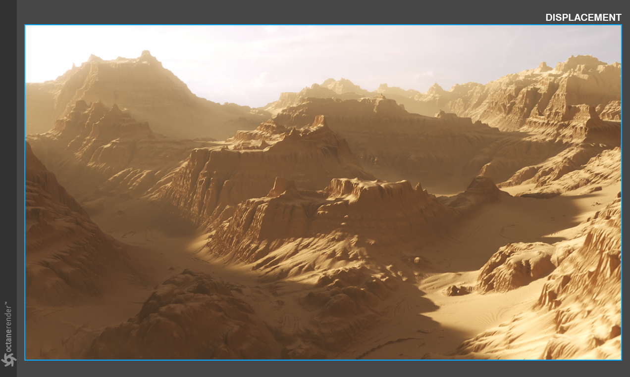
In the example above, only a subdivided plane was used to create the landscape, along with volume fog and another feature in Vertex Displacement, Auto-Bump (more on that later). Below you can see the attributes for Vertex Displacement. Let's break down the settings using the material we built for the scene above:
|
|
Vertex Displacement
|

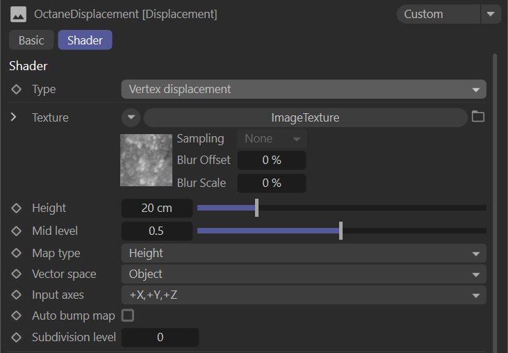
type
This menu allows you to choose between Texture and Vertex Displacement.
Texture
The displacement texture. All texture types are supported, including images, procedurals and OSL textures. Texture Displacement is driven by texture image and the node setting's resolution, while Vertex Displacement uses the mesh's data to achieve displacement.
Each have their own pros and cons.
Height
The displacement height.
Mid Level
The value in the image which corresponds to no displacement of the surface. The range is always normalized to [0,1]. Set this value to 0.5 for image textures that use 50% to represent no displacement.
Map Type
The displacement map type. Height maps (grayscale images) and Vector displacement maps are supported.
Vector Space
The vector displacement map space. Only valid if the Map Type is set to Vector. Tangent would be chosen when using a specialized vector displacement map, from a sculpting program, for instance.
Auto Bump Map
Generates an automatic bump map to achieve fine details, without requiring high subdivision levels. Only supported for Height displacement maps.
Subdivision Level
The subdivision level applied to polygons using this material. Overrides the subdivision level set in geometry preferences. Higher subdivision levels will achieve greater displacement detail but can also increase render and pre-processing times.
|
NOTE: For Image textures, set the Gamma to 1.0 to avoid holes in the geometry. The vertices should be shared between adjacent faces. |
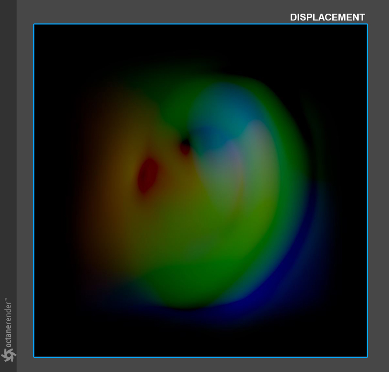
Let's start by looking at an example of a render using the Map Type: Vector. Height is the setting you'll likely use in most cases, giving you two directions of displacement, but Vector is omni-directional and can create actual convex/concave areas, especially when used with vector displacement maps and the Vector Space parameter set to Tangent. Let's first look at what one of these specialized maps look like that would typically come from a sculpting application:
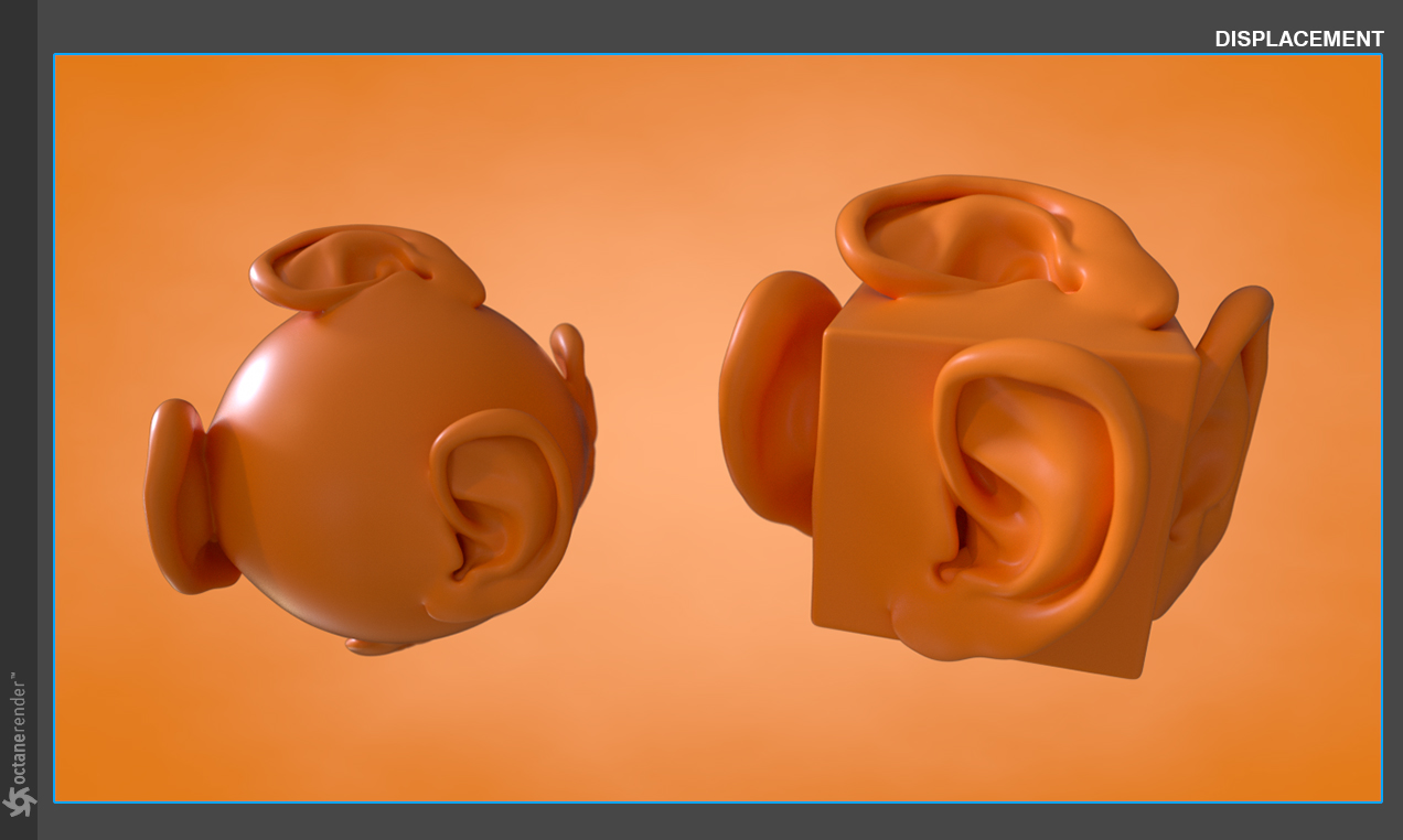
Below is a render using this map with the settings we defined above. The map is applied with a box projection on a simple parametric sphere and cube. As you can see, we're creating complex geometry from all angles with a single map.
Taking this a step further, we can use the Displacement Mixer node, and the ability to use triplanar mapping with displacement, to create something even more complex below:
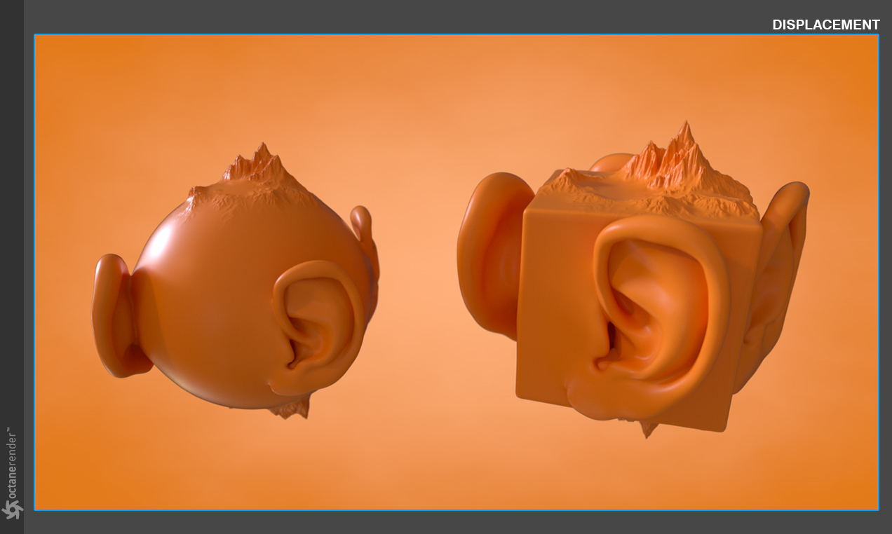
In the example above we used a terrain displacement map for the Y+/- areas of the meshes and then the ear vector displacement for the X+/-, Z+/- directions. As illustrated in the node layout below, we used different displacement nodes for each map, then pipe those into a Displacement Mixer node. We used an RGBSpectrum node set to black in the other Triplanar inputs so that the other axes were not displaced.
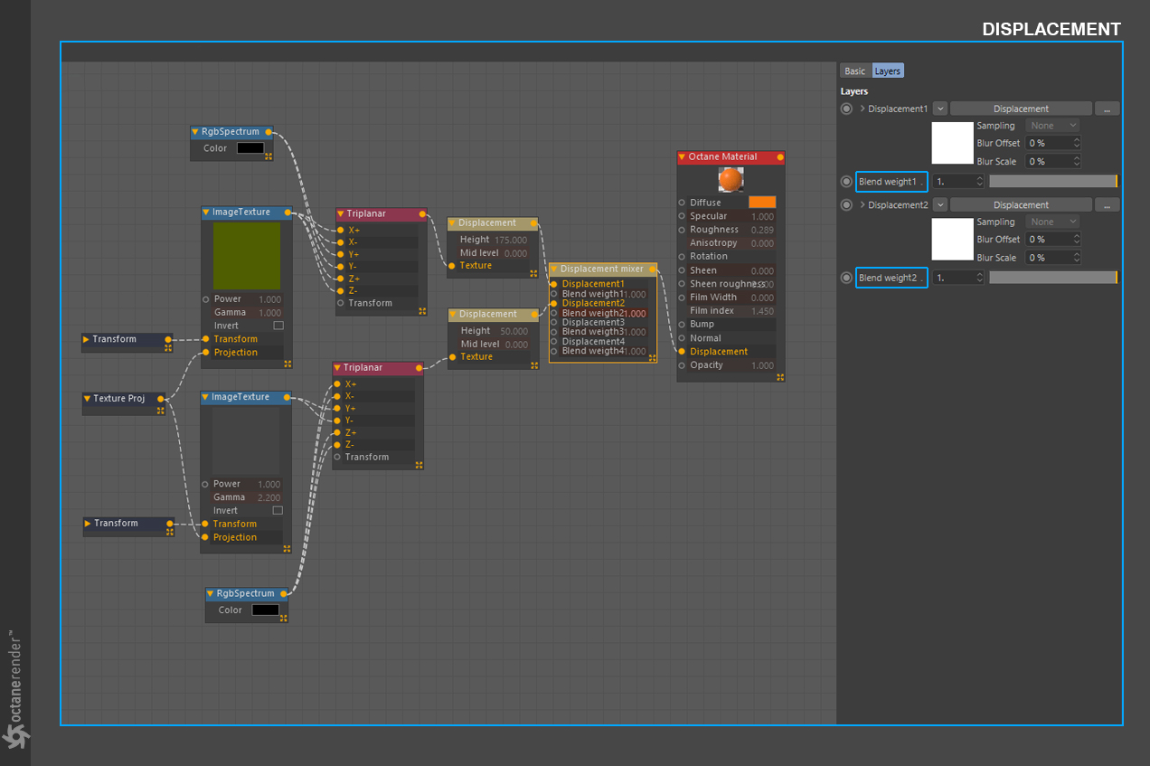
Expanding on the Displacement Mixer node that we used in the previous render, you can only mix Vertex Displacement. Texture Displacement does not work with the Displacement mixer. The Blend Weights, highlighted in the above image, are simply a power/intensity slider for the input above the slider.
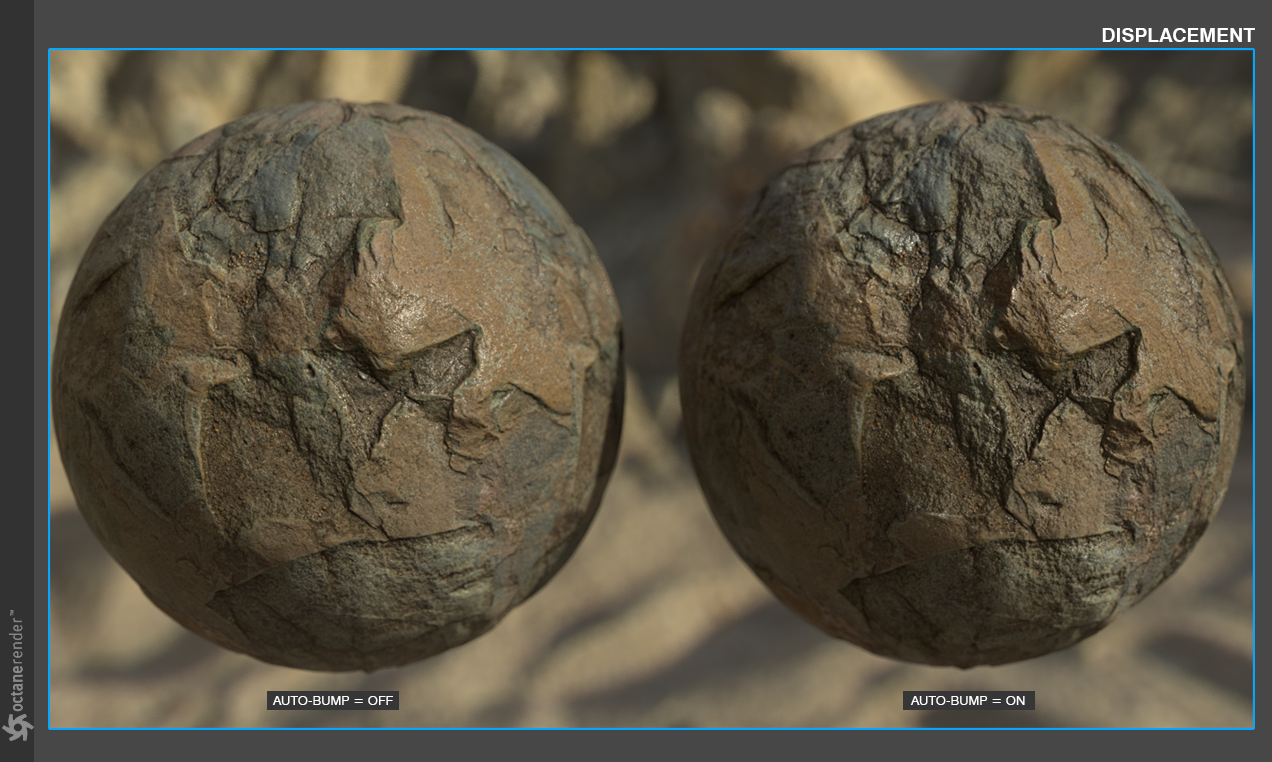
One of the last settings we're going to cover in this section is the Auto Bump Map. Below, you'll find a side-by-side comparison example of the difference when using the Auto Bump Map attribute. You can use lower subdivision levels and allow the extra detail to be added in via bump mapping with this parameter. The bump mapping works the same as if you were using the bump channel in the material, thus creating the illusion of extra detail, while not creating more polygons. In light of that, depending on the angle and distance from the camera, sometimes it will be in your best interest to raise the Subdivision Level for the extra detail you need.
More information on OSL in Octane can be found here.