OSL Camera
The OSL Camera node is a scriptable node. You can create custom camera types for any purpose (such as VR warping) with OSL (Open Shader Language) scripts. It is a flexible camera used to match the rendering to the existing footage. OSL is a standard created by Sony Imageworks. To learn about the generic OSL standard, information is provided from the OSL Readme and PDF documentation. To load an OSL Camera, a Shader Editor node material needs to be created with an OSL Camera node and then assign to the Camera Properties panel (figure 1). There is also an OSL Baking Camera node which provides a slightly different set of parameters.
|
|
OSL Camera
|

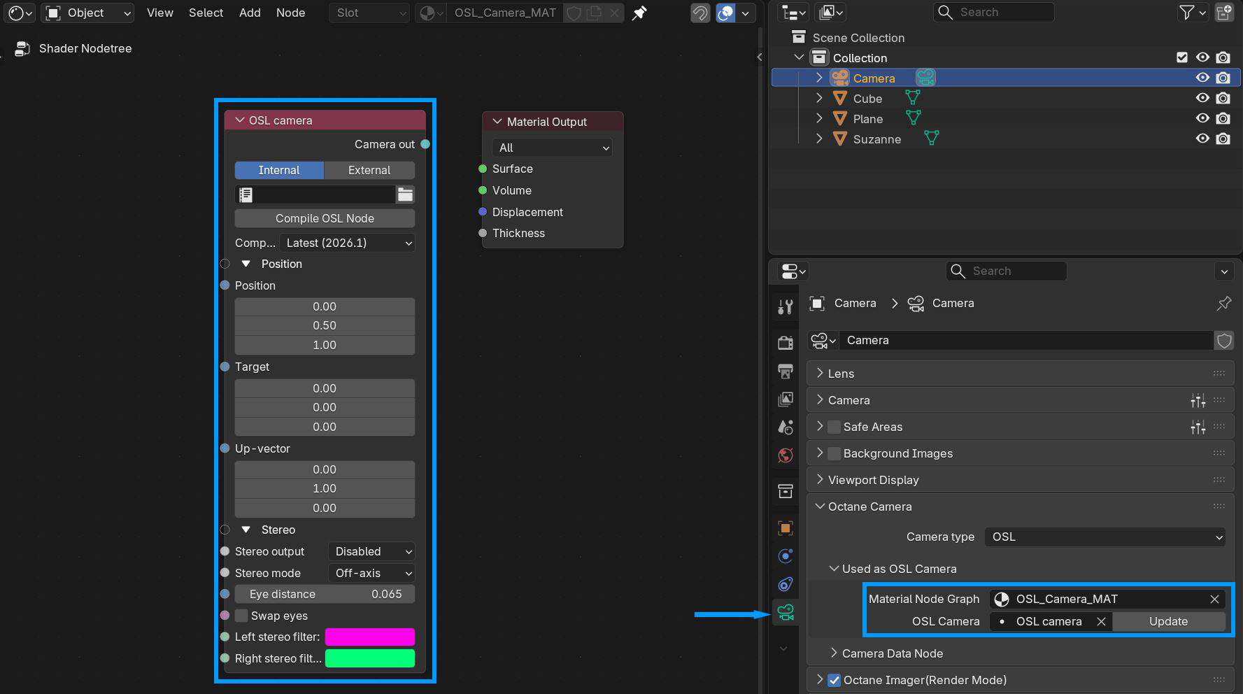
Figure 1: An OSL Camera node loaded into the Camera Properties
There are two options to add scripts for the OSL texture. The Internal option is available by opening another area in Blender® for the Text Editor, creating a new text, and writing the OSL script. The External option lets you to select a pre-coded OSL file from the File Explorer window.
You can create your own custom Camera using an OSL camera node. As a starting point, below is a basic OSL implementation of a Lens camera:
shader OslCamera(
float FocalLength = 1 [[ float min = 0.1, float max = 1000, float sliderexponent = 4]],
output point pos = 0,
output vector dir = 0,
output float tMax = 1.0/0.0)
{
float pa;
int res[2];
getattribute("camera:pixelaspect", pa);
getattribute("camera:resolution", res);
float u1 = 2 * (u - .5);
float v1 = 2 * (v - .5) * pa * res[1] / res[0];
pos = P;
vector right = cross(I, N);
dir = 2*FocalLength * I + v1 * N + u1 * right;
dir = transform("camera", "world", dir);
}
For a list of OSL variable declaration input/output types in the OSL Specification that OctaneRender® supports, refer to the Appendix topic on OSL Implementation in the OctaneRender® Standalone manual. To learn more about scripting within OctaneRender® using OSL, see to The Octane OSL Guide.
OSL Camera Parameters
Internal/External - Determines where the OSL code is created.
Compile OSL Node - Compiles the OSL code, internal or external.
Compatibility Version - The version of Octane this node should be compatible with.
Position
Position - Determines the position of the camera.
Target - The position the camera should look at.
Up Vector - The vector determing the up direction for the camera.
Stereo
Stereo Output - This specifies the output rendered in stereo mode.
- Left - Renders the left-eye image.
- Right - Renders the right-eye image.
- Side-By-Side - Renders the scene as a pair of two-dimensional images.
- Anaglyphic - View renders with red/blue 3D glasses.
- Over-Under - The two-dimensional images are placed one above the other for special viewers.
Stereo Mode - Enables stereo mode, and gives you options to use off-axis or parallel stereo camera projections.
Eye Distance - The distance between the left and right eye in stereo mode, measured in meters. This is also refers to the inter pupillary distance (IPD), stereo interocular distance, or stereo distance. When working with scenes for virtual reality, the IPD scale unit used by OctaneRender® is not affected by the scene scale unit. This is intentional, as when the IPD is set, this must remain consistent even when scenes change in scale or proximity. However, the units used by the IPD in OctaneRender® are also interpreted in meters, so when checking the Camera attribute, Eye Distance is effectively 0.02, which is its default value equal to 2 cm or 20 mm. For a distance of 65 mm, set the Camera node's Stereo Distance value to 0.065. For realistic depth, use values between 0.055 and 0.075.
Swap Eyes - Swaps the left and right eye positions when stereo mode shows both.
Left Stereo Filter/Right Stereo Filter - The left and right filter colors used to create the anaglyphic stereo effect in the render.
OSL Baking Camera Parameters
Internal/External - Determines where the OSL code is created.
Compile OSL Node - Compiles the OSL code, internal or external.
Compatibility Version - The version of Octane this node should be compatible with.
Baking Group ID - Specifies the group ID to bake. By default, all objects belong to the default baking group number 1.
UV Set - This determines the UV coordinates to use for baking.
Size - The number of pixels added to the UV map edges. The padding size is specified in pixels. The default padding size is set to 4 pixels, with 0 being the minimum and 16 being the maximum size.
Edge Noise Tolerance - Helps remove hot pixels appearing near the UV edges. Values close to 1 do not remove any hot pixels, while values near 0 attempts to remove them all.
Continue if Transparent - Changes the handling of transparency on the first surface hit of a path. If disabled, a transparent surface will terminate the path.