The Layered material node constructs complex materials that consist of a base layer and up to eight MaterialThe representation of the surface or volume properties of an object. Layers. You can create complex materials in a physically-based manner, as opposed to manually mixing materialsUsed to mix any two material types. together.
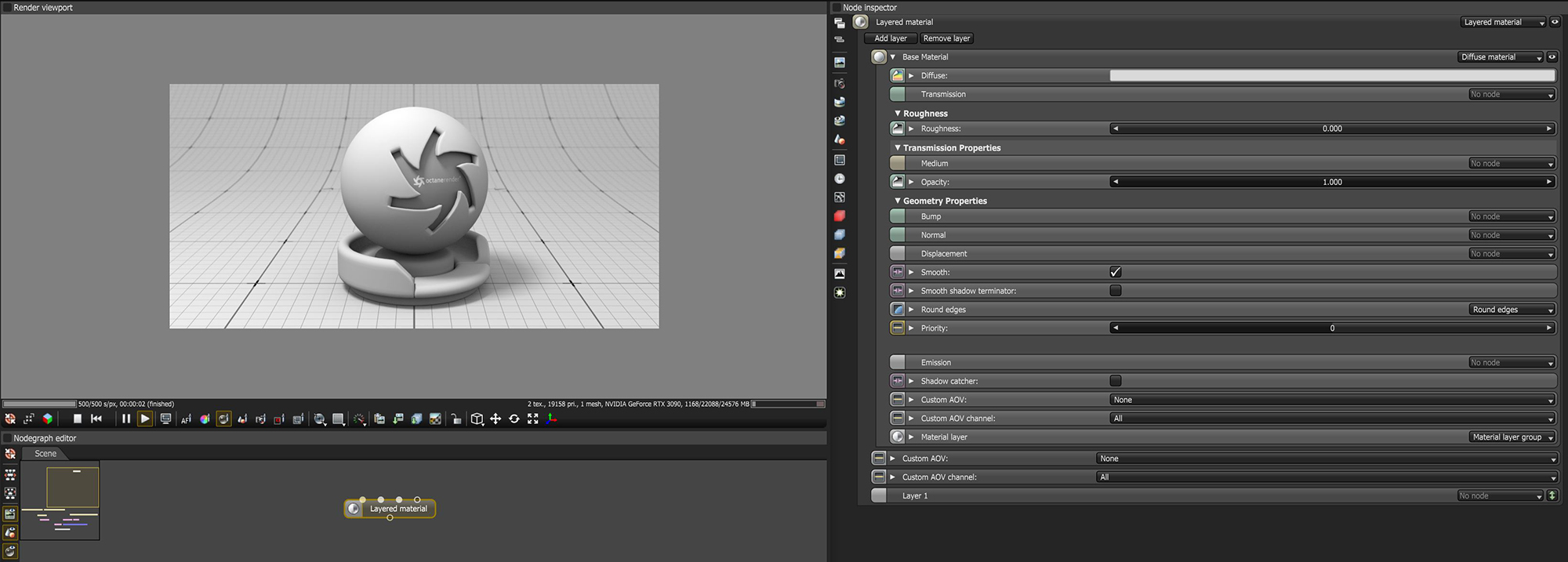
Figure 1: Layered material node parameters
Add Layer - Adds a new Layer input to the end of the Node. You can add up to eight Layer inputs.
Remove Layer - Removes the last Layer input on the node.
Base Material - The material that sits below any additional Material Layers.
Layer 1-8 - The Material Layer inputs.
With the Layered material, you are given all Material Layers used in OctaneRender®, allowing you to reconstruct pre-existing Octane materials or your own uber-material.
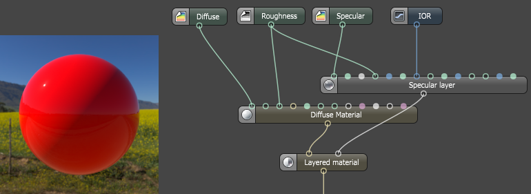
Figure 2: Recreating the GlossyThe measure of how well light is reflected from a surface in the specular direction, the amount and way in which the light is spread around the specular direction, and the change in specular reflection as the specular angle changes. Used for shiny materials such as plastics or metals. Material by using a Diffuse materialUsed for dull, non-reflecting materials or mesh emitters. and a SpecularAmount of specular reflection, or the mirror-like reflection of light photons at the same angle. Used for transparent materials such as glass and water. layer
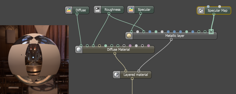
Figure 3: Recreating the Metallic material by using a DiffuseAmount of diffusion, or the reflection of light photons at different angles from an uneven or granular surface. Used for dull, non-reflecting materials or mesh emitters. material and Metallic layer
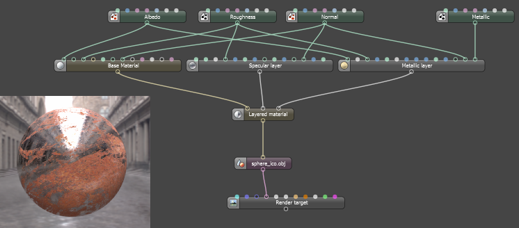
Figure 4: A simple PBRA contemporary shading and rendering process that seeks to simplify shading characteristics while providing a more accurate representation of lighting in the real world. metallic/roughness workflow
Diffuse- Provides color to the material. This is also known as base color or albedo. You can set Diffuse color by using a value, or connecting a Procedural or Image texture.
TransmissionA surface characteristic that determines if light may pass through a surface volume.- Uses a color or texture that is mixed with the material’s Diffuse color, and is most noticeable in areas affected by indirect lighting.
Roughness - Determines the spread of highlights on the surface. A high Roughness value or light color can simulate very rough surfaces such as sand paper or clay. You can set Roughness using a value, or by connecting a Procedural or Image texture. A roughness value of 1 (white color) creates a diffuse sheen along the edges of the surface, simulating the look of crushed velvet.
Medium- OctaneRender® has three types of mediums to create translucent surfaces:
Opacity - Determines what parts of the surface are visible in the render. Dark values indicate transparent areas, and light values indicate opaque areas. Values in-between light and dark indicate semi-transparent areas. You can lower the Opacity value to fade the object's overall visibility, or you can use a Texture map to vary the opacity across the surface. For example, if you want to make a simple polygon plane look like a leaf, you would connect a black-and-white image of the leaf’s silhouette to the Opacity channel of the Diffuse shader. When using an Image texture map, set the Data Type to Alpha Image if the image has an alpha channel, or Grayscale Image for black-and-white images, to load an image for setting the transparency. To invert the transparency regions, use the image's Invert checkbox.
Bump - Creates fine details on the material’s surface using a Procedural or Image texture. Often a Greyscale image texture connects to this parameter - light areas of the texture indicate protruding bumps, and dark areas indicate indentation. You can adjust the Bump map's strength by adjusting the Power or GammaThe function or attribute used to code or decode luminance for common displays. The computer graphics industry has set a standard gamma setting of 2.2 making it the most common default for 3D modelling and rendering applications. values on the Image texture node. These attributes are covered in more detail in the Texture topic in this manual.
Normal - Creates the look of fine detail on the surface. A Normal map is a special type of Image texture that uses red, green, and blue color values to perturb the surface normals at render time, giving the appearance of added detail. They can be more accurate than Bump maps, but require specific software such as ZBrush®, Mudbox®, Substance Designer, xNormal, or others to generate. To load a full-color Normal map, set the Normal channel to the RGB Image data type. Note that Normal maps take precedence over Bump maps, so you cannot use a Normal map and a Bump map at the same time.
DisplacementThe process of utilizing a 2D texture map to generate 3D surface relief. As opposed to bump and normal mapping, Displacement mapping does not only provide the illusion of depth but it effectively displaces the actual geometric position of points over the textured surface. - Adjusts the height of a surface's vertices at render time using a texture map. Displacement maps differ from Bump or Normal maps in that the geometry is altered by the texture, as opposed to just creating the appearance of detail. Displacement mapping is more complex than using a Bump or Normal map, but the results are more realistic, especially along a surface's silhouette. Displacement only works with the Texture Image node, and the displaced mesh must have UV Texture coordinates. Other Texture nodes, such as Turbulence or Marble, will not work with Displacement. For more information, see the Texture Overview topic in this manual.
Smooth - Smooths out the transition between surface normals by blending the polygon edges together. If this option is disabled, the edges between the polygons of the surface appear sharp, giving the surface a faceted look.
Smooth Shadow Terminator - If enabled, self-intersecting shadows are smoothed according to the polygon's curvature.
Round Edges - Rounds the geometry edges by using a shading effect instead of creating additional geometry. See the Round Edges topic in this manual for more information.
Priority - Used to resolve the ambiguity in overlapping surfaces, the surface priority control allows artists to control the order of preference for surfaces. A higher number suggests a higher priority for the surface material, which means it is preferred over a lower priority surface material if a ray enters a higher priority surface and then intersects a lower priority surface while inside the higher priority surface medium.
Emission - Also known as a Mesh emitter, this creates a surface that emits light. To activate an emission, connect the Emission input of the Diffuse material to either a Blackbody or a Texture emission map. The Textures and the Mesh Emitters (under Lighting Overview) topics in this manual cover maps in more detail.
Shadow CatcherThe Shadow Catcher can be used to create shadows cast by objects onto the surrounding background imagery. The shadows cast are not limited to simply a ground plane but can be cast onto other surfaces of varying shapes. - Converts the material into a Shadow Catcher, which is visible in areas that are in shadows. All other areas are transparent in the render.
Material Layer - Adds a Material Layer above the base material. See the Material Layers topic in this manual for more details.
Custom AOV - Writes a mask to the specified custom AOV.
Custom AOV Channel - Determines whether the custom AOV is written to a specific color channel (R, G, or B) or to all the color channels.
NOTE: There is also a Custom AOV and Custom AOV Channel parameter that applies to the entire Layered Material node.