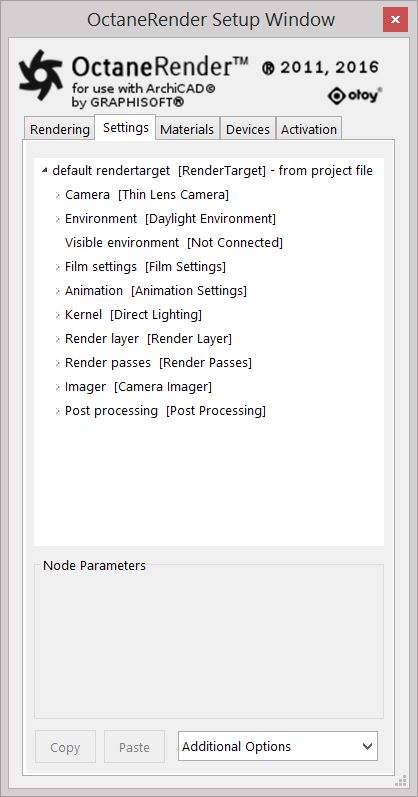
A RenderTarget is the node that is referenced as an output point for the rendered scene. It offers powerful flexibility especially when setting up advanced scenes as it hooks up to everything that forms part of the scene including the environment, camera, and the render kernel.
When using the OctaneRender for ArchiCAD plugin, the ArchiCAD scene is automatically assigned a default RenderTarget Node in order for Octane to render it. A camera/view is also connected to the Rendertarget Node by default.
You can click on other nodes connected to the RenderTarget to enable the edit options available for that node in the Node Parameters window.
Figure 1: The default RenderTarget node
Camera
This node holds all Octane camera controls of the plugin. The Octane camera position, target, up vector and FOV (Field of View) are all taken from the current ArchiCAD camera. Only non-orthographic cameras can be rendered in the Octane Render Viewport.
The Thin Lens camera is the primary node type and commonly used camera but there are also other types meant for other purposes such as the Panoramic Camera and the Baking Camera.
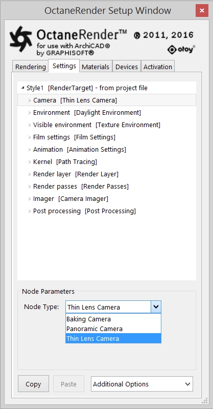
Figure 2: The Camera Node parameters
Camera settings are described in greater detail in the section on Cameras in this manual.
Environment
The lighting in the scene can be set through the Environment Node and specifying the type to Daylight, Texture or Planetary environment (Figure 3). When lighting is generated using the environment by Daylight, the sun direction is not set in the Octane plugin. If the Octane ‘environment’ node is set to ‘daylight’, then the Octane sun position is taken from the ArchiCAD sun position, so use the ArchiCAD ‘Settings’ button to adjust the ArchiCAD sun position, which will immediately reposition the Octane sun.
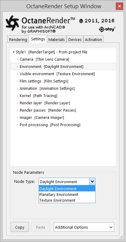
Figure 3: The Environment Node parameters
Environment settings are described in greater detail in the section on Lighting in this manual.
Visible Environment
The visible environment overrides the normal environment in some specific use cases, giving more control over the final look of the render. If a medium is configured in the environment, the medium will be ignored when the environment is used as a visible environment.
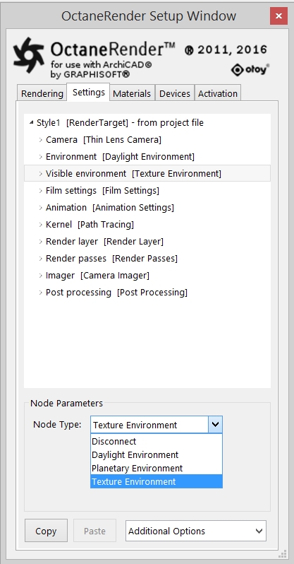
Figure 4: The Visible Environment Node parameters
Refer to Chapter ‘Lighting → Visible Environment for more information.
The rendering resolution (and region) of the scene can be set in the Film Settings Node.
Refer to Chapter ‘Rendering’ → ‘Film Settings’ and Chapter ‘Workflow’ → ‘Set Rendering Resolution’ for more information.
Animation
The Animation Settings Node is used to control the shutter interval. It exposes the attributes where blur effects can be applied. This attributes include the shutter time, shutter alignment and subframe portions of animated frames.
Refer to sections ‘Rendering → Animation’ and ‘Effects → Motion BlurAn optical phenomenon that occurs when a camera’s shutter opens and closes too slowly to capture movement without recording a blurring of the subject.’.
Kernel
There are four major rendering kernels in OctaneRender: Direct Lighting, Path Tracing and PMC and Infochannels Kernel (sometimes called Deep Channel Kernel). They are switchable by changing the type in the Node Type selection box.
In general, the default type, Direct Lighting, is used for drafts although can also be used for final copy (i.e. for a lot of exterior scenes). Path Tracing and PMC are used for high quality rendering and it is recommended for interior scenes. Finally, the Infochannels Kernel is used for analytical output and it is also useful for postproduction).
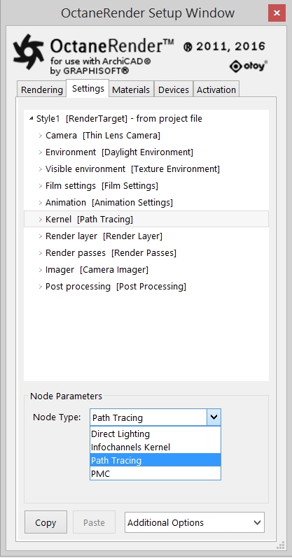
Figure 5: The Kernel Node parameters
Refer to Chapter ‘Rendering’ → ‘KernelsBy definition, this is the central or most important part of something. In Octane, the Kernels are the heart of the render engine.’.
Render Layer
Render layers allow users to separate their scene geometry into one parts, where one part is meant to be visible and the rest of the other parts “capture” the side effects of the visible geometry.
Note: In the ArchiCAD plugin, Render LayersRender layers allow users to separate their scene geometry into parts, where one part is meant to be visible and the rest of the other parts “capture” the side effects of the visible geometry. The layers allow different objects to be rendered into separate images where, in turn, some normal render passes may be applied. The Render layers are meant for compositing and not to hide parts of the scene. cannot be used.
Refer to Chapter ‘Rendering → Render Layers’.
Render Passes vary among render engines but typically they allow an image to be separated into its fundamental visual components such as diffuse, ambient, specular, etc.
This allows you to segregate the different aspects of the scene, respectively rendering each aspect across multiple images. This is particularly useful in fine-tuning projects, compositing, and creating remarkably detailed and photo-realistic images.
Refer to Chapter ‘Rendering → Render Passes’.
The (Camera) Imager setting provide useful parameters for post-rendering adjustments such as Exposure, GammaThe function or attribute used to code or decode luminance for common displays. The computer graphics industry has set a standard gamma setting of 2.2 making it the most common default for 3D modelling and rendering applications. and Vignetting.
Refer to Chapter ‘Cameras → Camera Imager Settings’.
Post processing
Additional to the (Camera) Imager the Post processing node provides useful post-processing effects on the resulting render such as Bloom and Glare.
Refer to Chapter ‘Effects → Post processing.