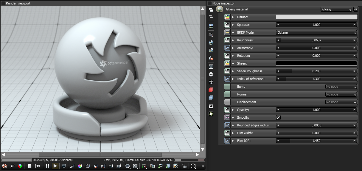
The Glossy material is used for shiny materials such as plastics or metals.
Figure 1: The OctaneRender® Glossy material
BRDF Model- The BRDF (Bidirectional Reflectance Distribution Function) determines the amount of light that a material reflects when light falls on it. For Glossy materials, you can choose from four BRDF models. Specific geometric properties (the micro-facet distribution) of the surface affects each BRDF, which describes the surface's microscopic shape (i.e. micro-facet normals) and scales the brightness of the BRDF's reflections. Refer to the topic on BRDF Models for more information.
|
Octane 3.07 |
Beckmann |
|
GGX |
Ward |
Figure 24: The four BRDF Models applicable to Glossy materials
Anisotropy - Controls the material's reflectance uniformity. Reflectance changes based on surface orientation or rotation is anisotropic. If the reflectance is uniform in all directions and doesn't change based on the surface's orientation or rotation, then it is isotropic. This parameter's default value is 0, which sets the metallic material as isotropic. Non-zero values mean the material exhibits anisotropic reflectance, where -1 is horizontal and 1 is vertical.
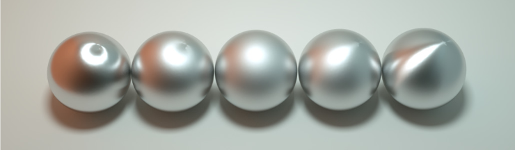
Figure 35: Anisotropic roughness exemplified in materials like brushed metal
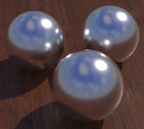
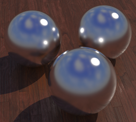
Index of Refraction- Determines the reflection strength on the surface based on Fresnel's law. With a value greater than 1, reflection is strongest on the surface parts that turn away from the viewer's angle (grazing angles), while the reflection appears weaker on the surface parts perpendicular to the viewing angle. This results in a more realistic-looking surface. With a value lower than 1, the Fresnel effect is disabled, and the reflection color appears as a uniform color across the highlight. The Specular channel's color determines the reflective highlight's color.
In the following examples, the six balls have a roughness of 0, 0.2, 0.4, 0.6, 0.8, 1.0 (left to right) and only the Specular value and Index of Refraction parameters are modified for each rendered image (see Figure 3).
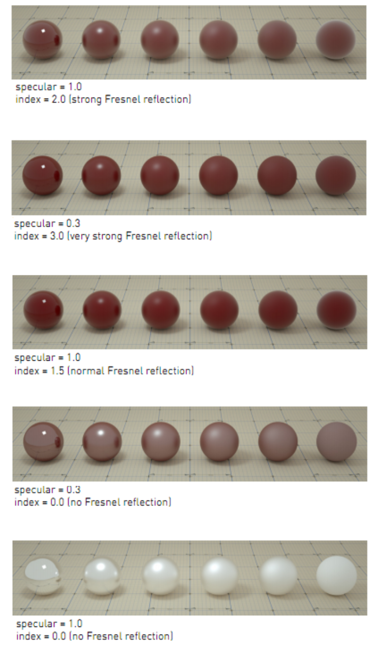
Figure 43: Spheres rendered using different settings for specular and index