Vertex DisplacementThe process of utilizing a 2D texture map to generate 3D surface relief. As opposed to bump and normal mapping, Displacement mapping does not only provide the illusion of depth but it effectively displaces the actual geometric position of points over the textured surface. is a more robust displacement system that doesn't suffer from the same limitations as Texture Displacement. It works with all TexturesTextures are used to add details to a surface. Textures can be procedural or imported raster files. and ProjectionsMethods for orienting 2D texture maps onto 3D surfaces., including Procedurals, OSL textures, and images. Height maps and Vector Displacement maps are also supported, and can be mixed using the Vertex Displacement mixer node.
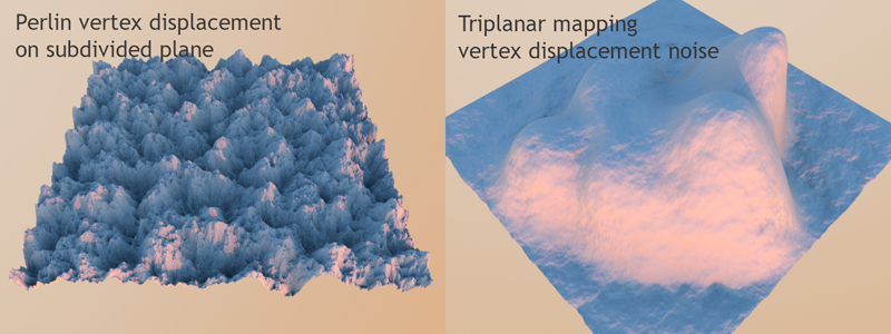
Figure 1: Perlin Vertex Displacement on a subdivided plane (left); Triplanar mapping Vertex Displacement noise (right)
Vertex Displacement subdivides the source Mesh based on the subdivision level. This can introduce higher mesh complexity that may increase render time and pre-processing per subdivided Mesh.
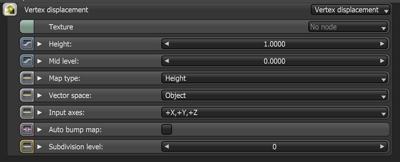
Figure 2: Vertex Displacement node parameters
Texture - All texture types are supported, including Images, Procedurals, and OSL textures.
Height - The displacement height in meters.
Mid Level - The image value that corresponds to no displacement. The range is always normalized to [0,1]. Set this value to 0.5 for image textures that use 50% to represent no displacement.
Map Type - Choose between Height maps and Vector Displacement maps.
Vector Space - Valid when Map Type is set to Vector Displacement.
Input Axis - Provides information regarding how to interpret RGB data, this setting is only valid with the Vector map type.
Auto Bump Map - Generates an Automatic bump map to achieve fine details without requiring high subdivision levels. Only supports Height displacement maps.
Subdivision Level - The subdivision level applied to polygons using this material. Overrides the subdivision level set in Geometry preferences. Higher subdivision levels achieve greater displacement detail, but can also increase rendering and pre-processing times.
NOTE: For Image textures, set the GammaThe function or attribute used to code or decode luminance for common displays. The computer graphics industry has set a standard gamma setting of 2.2 making it the most common default for 3D modelling and rendering applications. to 1.0 to avoid holes in the geometry. The vertices should be shared between adjacent faces.
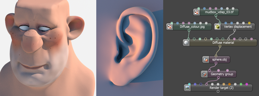
Figure 3: An example of a Vector Displacement map, which works in tangent space