AbsorptionDefines how fast light is absorbed while passing through a medium. is controlled with the absorption node (figure 1), which defines how fast light is absorbed while passing through a medium.

Figure 1: The Absorption Medium parameters as seen in the NodeGraph Editor.
Absorption Parameters
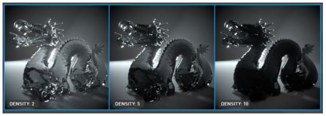
Density - Controls the absorption density. A higher value will absorb more light (figure 2).

Figure 2: Increasing the Density parameter.
Volume Step Length - Depending on the surface, you may need to adjust this parameter. The default value is 4, but if the volume is smaller than this, you need to decrease the value. Decreasing this value decreases render speed, and increasing the value causes the ray marching algorithm to take longer steps. If the Volume Step Length exceeds the volume's dimensions, then the ray marching algorithm takes a single step through the whole volume. To get the most accurate results, keep Volume Step Length as small as possible.
Volume Shadow Ray Step Length - Step length that is used by the shadow ray for marching through volumes.
Use Volume Step Length for Volume Shadow Ray Step Length - Check box for using the Volume Step Length for the Volume Shadow Ray Step Length as well.
Sample Position DisplacementThe process of utilizing a 2D texture map to generate 3D surface relief. As opposed to bump and normal mapping, Displacement mapping does not only provide the illusion of depth but it effectively displaces the actual geometric position of points over the textured surface. - Allows a texture to control a volume's sample positions displacement.
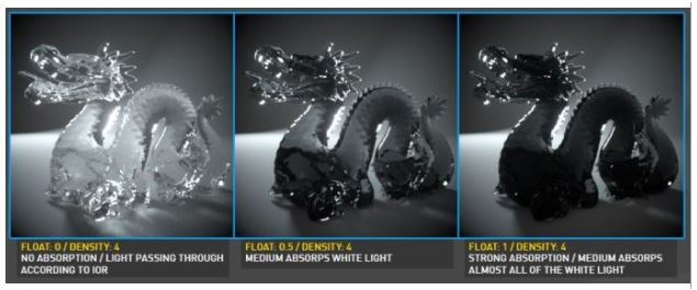
Absorption - Determines the absorption value of the material by assigning a texture. This can be either a grayscale or color texture. When using greyscale values, 0 (black) means that there is no absorption. Values greater than zero determine how quickly the medium absorbs white light (figure 3).

Figure 3: Using a grayscale value to control absorption.
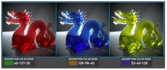
Absorption can also be controlled using color values. The observed color is the complementary color (opposite color) of the specified color value (figure 4).

Figure 4: Using color values to determine absorption.
Invert Absorption - Inverts the absorption value allowing the specified absorbed color to be the actual color that is visible.
The Schlick node can be used to control which direction the scattering occurs.