
The Scatter node creates multiple instances of its input. In this context it is important not to confuse the scattering geometry node with the scattering medium node.
The power of the Scatter node is that it is extremely efficient and its possible to load an almost unlimited number of instances into OctaneRender. This is perfect for working with scenes that have large numbers of trees, gravel, buildings, and other objects. Figure 1 shows a scene that uses Scatter nodes to place rocks and plants.
Figure 1: Scatter nodes are used to place a large number of rocks and trees
To use this feature, the original geometry that will be instanced must be imported into OctaneRender along with a file that contains the data of each transform matrix that represents the linear transformation of each of the instances. The resulting data in the Scatter node is a long list of values that tells OctaneRender how and where to place each individual instance. The transform matrices (or “transforms” may be contained in a special CSV file. These files are usually generated using plugins or scripts and a 3D app such as Maya or 3DS Max.
The scene in Figure 2 was created using the 3DS Max scatter plugins MultiScatter from iCube R&D, and Forest Pack from iToo Software.
Using the Scatter Node
The first step is to set up the scene in the host 3d application (3DS Max, Maya, C4D, etc.) then use a particle system or plugin to arrange the instances in the scene. Then export the instanced geometry (a single rock, tree, blade of grass, etc.) as well as the CSV file which contains the transform of each instance.
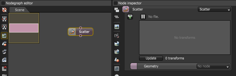
In OctaneRender, the original mesh needs to be imported and then a Scatter node needs to be added to the scene (Figure 2).
 .
.
Figure 2: Add the Scatter node to the OctaneRender scene
The Instanced geometry is then connected to the Scatter node (Figure 3).
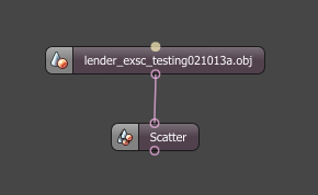
Figure 3: A Scatter node is connected to an imported Geometry node
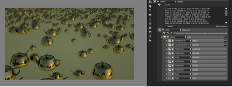
Select the Scatter node and take a look at its attributes in the Node Inspector. Click on the drawer icon in the upper left of the Scatter parameters and use the file browser to locate the CSV file exported from the host application. Once this is connected the instanced geometry will be scattered throughout the scene (Figure 4).
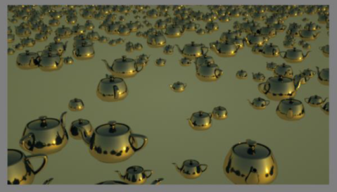
Figure 4: The CSV file places instances of the teapot geometry throughout the scene
How Octane Reads A Single Transform
Each coordinate in a Scatter node represent the first three rows of a transformation matrix (the fourth is always [0, 0, 0, 1]). Each coordinate therefore has 12 float values from a transform matrix and then a 13th value is added to specify the Instance ID for that coordinate. The value for the Instance ID is user-defined, and this may automatically be provided by the integrated plugins, or generated by a lua script, or explicitly placed by the user through the transforms parameter of the scatter node or via a csv file. If there is no value provided for the Instance ID, as in earlier versions of Octane (3.06.x), the Instance ID will be set to -1 by default.
For example the transform matrix for a 30° rotation around the Z axis looks like this:
![]()
The coordinate in the Scatter node should contain these 13 values:
![]()
For a translation:
![]()
The scatter node will contain these 13 values: 1 0 0 tx 0 1 0 ty 0 0 1 tz -1
As the elements in the transform matrix changes, each change will represent an individual transform. All the transforms then have to be exported from modeling applications. The CSV file then needs to be loaded into the Scatter node. Prior to loading the CSV file into OctaneRender, note the differences between the acceptable csv structures for versions of OctaneRender.
The Evolution of Scatter Data in CSV Files
Users may format their own csv files so that these may be used for assigning Instance IDs to each of the Transforms.
From v3.07, an enhanced CSV structure for the Scatter node is introduced to accommodate user-defined Instance IDs set for each instance in a scatter node. The earlier structure is also supported however the Instance IDs will be set to -1 in the older structure.
CSV structure version 1 (used in Octane v3.06.x and earlier versions): A Transform is generated from every 12 float values in the file.
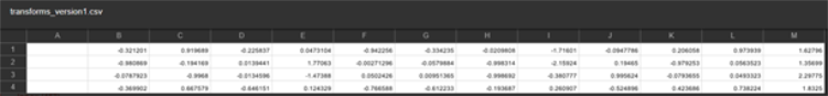
Figure 6: Used in Octane V3.06.x and earlier versions, a CSV file containing four transforms
CSV structure version 2 (used in OctaneRender v3.07): Each row that represents a single Transform in OctaneRender still has the 12 float values with one float value per column. However, this time it is required that a header should be placed for each column and then a 13th column called “ID” should also be placed. Figure 7 shows a CSV file with 13 columns named M00, M01, M02, M03, M10, M11, M12, M13, M20, M21, M22, M23 and ID.
Each header name, from M00 to M23, suggests that these are the float values that represents each necessary element of the transform matrices. Each row is then used to regenerate each of the transforms in Octane and the 13th column, called ID, is used to assign the user Instance ID for the transform represented by that row. The data should be separated by a comma, tab or space.
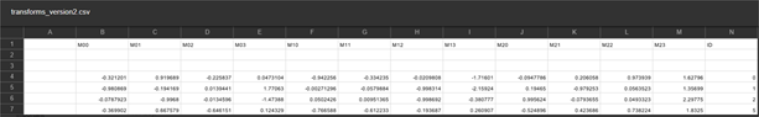
Figure 7: Used in OctaneRender V3.07.x, a CSV file containing four transforms and the user Instance ID per transform