Vertex DisplacementThe process of utilizing a 2D texture map to generate 3D surface relief. As opposed to bump and normal mapping, Displacement mapping does not only provide the illusion of depth but it effectively displaces the actual geometric position of points over the textured surface. is a more robust displacement system that does not suffer from the same limitations as Texture Displacement. It works with all TexturesTextures are used to add details to a surface. Textures can be procedural or imported raster files. and ProjectionsMethods for orienting 2D texture maps onto 3D surfaces., including Procedurals, OSL textures, and images. Height maps and Vector Displacement maps are also supported, and can be mixed using the Vertex Displacement Mixer node.
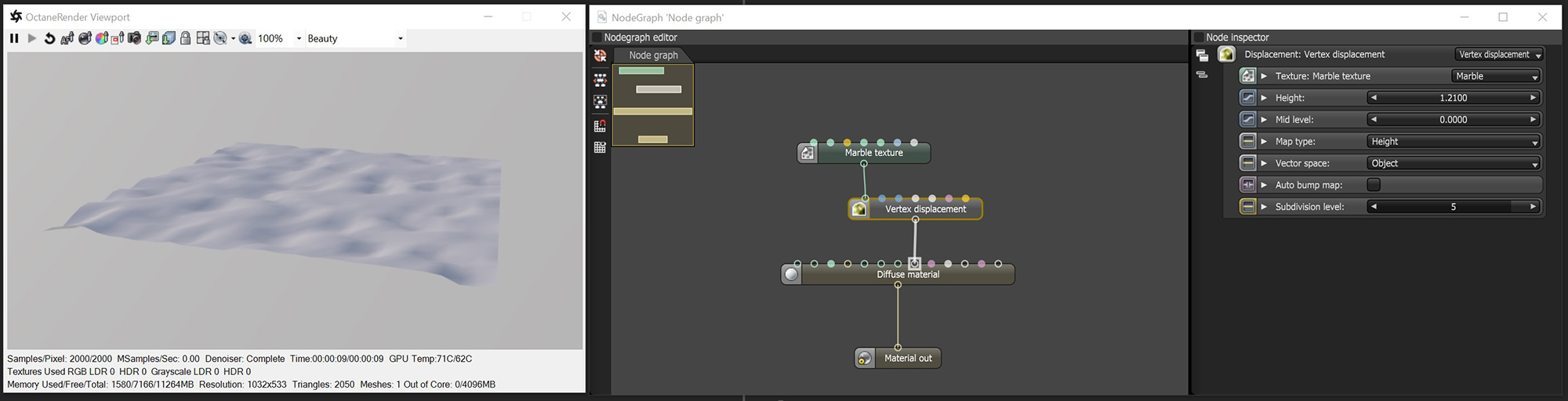
In the following illustration (figure 1), the NodeGraph Editor window is used to clearly illustrate the association of the various texture nodes.
Figure 1: The Vertex Displacement node used to displace a surface using a procedural Marble Texture node.
Texture
All texture types are supported, including Images, Procedurals, and OSL textures.
Height
The displacement height in meters.
Mid Level
The image value that corresponds to no displacement. The range is always normalized to [0,1]. Set this value to 0.5 for image textures that use 50% to represent no displacement.
Map Type
Choose between Height maps and Vector Displacement maps.
Vector Space
Valid when Map Type is set to Vector Displacement.
Auto Bump Map
Generates an Automatic bump map to achieve fine details without requiring high subdivision levels. Only supports Height displacement maps.
Subdivision Level
The subdivision level applied to polygons using this material. Overrides the subdivision level set in Geometry preferences. Higher subdivision levels achieve greater displacement detail, but can also increase rendering and pre-processing times.
NOTE: For Image textures, set the Gamma to 1.0 to avoid holes in the geometry. The vertices should be shared between adjacent faces.