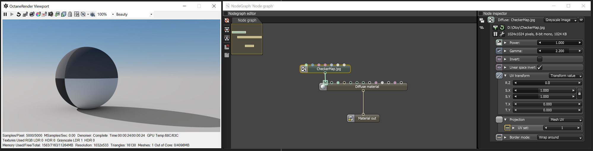
The Greyscale image converts an RGB image to grayscale (figure 1). This can conserve RAM when you're using a color image as an input for Bump or Opacity channels of an OctaneRender® material. The Invert checkbox inverts the image (useful for Bump and Opacity maps). In the following illustration, the NodeGraph Editor window is used to clearly illustrate the association of the various texture nodes.
Figure 1: The Greyscale Image node used to convert an imported texture map to greyscale.
Power
Controls image brightness. Lower values cause the image to appear darker. When used as a Bump map, this setting alters the bump height on the surface.
GammaThe function or attribute used to code or decode luminance for common displays. The computer graphics industry has set a standard gamma setting of 2.2 making it the most common default for 3D modelling and rendering applications.
Controls the input image luminance, and it also tunes or color-corrects the image.
Invert
Inverts the texture values.
Transform
Positions, rotates, and scales the surface texture.
Projection
Accepts OctaneRender®Projection nodes. If nothing is connected to this input, the Image texture uses the surface's UV texture coordinates by default. This also changes the UV set if the original surface contains more than one UV set.
Border Mode
Sets the behavior of the space around the image if it doesn't cover the entire geometry. Wrap Around is the default behavior, which repeats the image in the areas outside the image's coverage. If you set this parameter to White Color or Black Color, the area outside the image turns to white or black, respectively.