Any emitters in your scene will be very low-polygon (ie. not high density meshes). You can use the standard Revit lighting objects as emitters, or add low-poly geometry in place of the light geometry. All light emitter materials should be setup with a very low opacity (i.e., approx 0.1).
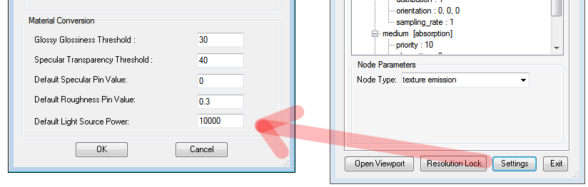
Revit Geometry with a material named “Default Light Source” will automatically be converted to blackbody emitters. The default emitter power of this material can be set in the plugin Settings (Default Light Source Power).
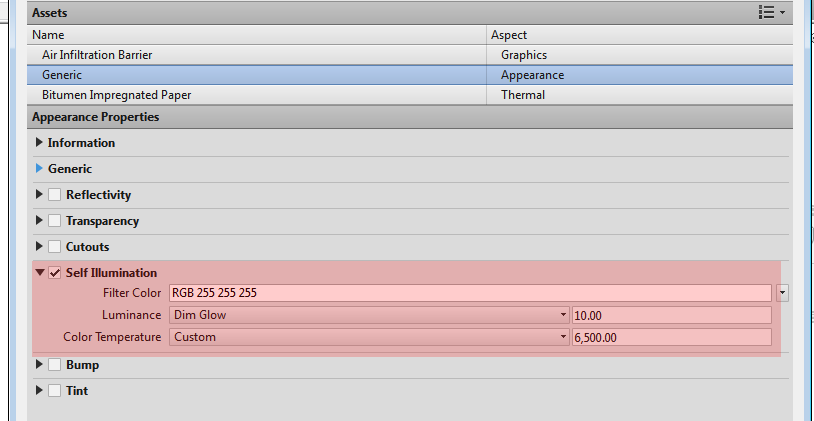
Revit Geometry with a material which has “Self Illumination” ON and a “Luminance” > 0 will also be converted to blackbody emitters, the power of which is determined from the Luminance setting, and the temperature from the Revit Color Temperature setting.
IESAn IES light is the lighting information representing the real-world lighting values for specific light fixtures. For more information, visit http://www.ies.org/lighting/. Lighting
It is highly recommended that all emitter materials be setup with an IES distribution. This allows the emission of light to be distributed to certain parts of the scene. IES files can be downloaded from various sources.
With no IES file plugged into the “distribution” pin, the light spreads equality in all directions from the lamp.
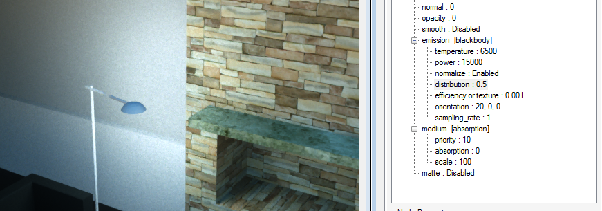
With an IES distribution file plugged into the “distribution” pin (as an “image” node), the light now only goes down. The direction of light can be controlled by the “orientation” pins. An “orientation” of 0, 0, 0 points the light direction down.
