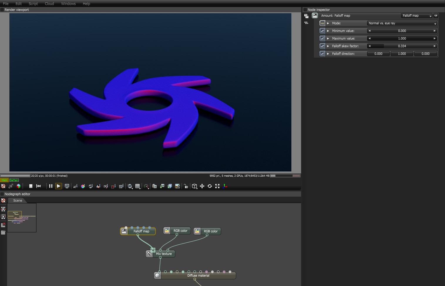
The Falloff Map texture controls material blending, depending on the viewing angle of the material's geometry.
Figure 1: The Falloff Map texture used to control the blending of two RGB Color nodes connected to a Mix Texture node
The angle between the Eye Ray and the Shading Normal is mapped from [0°, 90°] to [0, 1]. For values larger than 1, the Falloff node does a gamma correction using the Falloff Skew Factor as an exponent. OctaneRender® uses the Skew Factor to interpolate between the spectral shades resulting from the Minimum Value and Maximum Value parameters, which are based on the first and second inputs of a Mix node.
You can use the Falloff Map to control the Mix node's Amount parameter. The Mix node can either be Mix Texture or Mix MaterialThe representation of the surface or volume properties of an object..
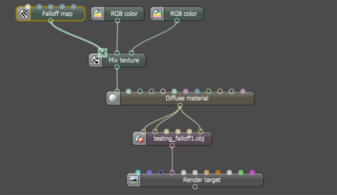
Figure 2: Falloff Map connected to a Mix Texture node
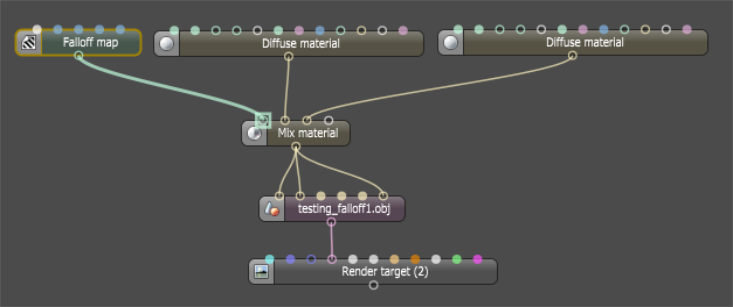
Figure 3: Falloff Map connected to a Mix MaterialUsed to mix any two material types. node
Falloff Map Parameters
Normal vs. Eye Ray - This is the default mode where OctaneRender® calculates the falloff from the angle between the Surface Normal and the Eye Ray. This mode is often used for reflections. The Falloff color range affects faces directly in front of the view, and gradually falls at angled faces towards the sides as it falls away from the straight-on viewing angle. The Falloff Direction parameter does not apply.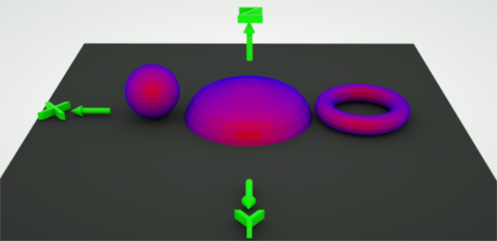
Figure 4: Skew factor = 1; Direction does not apply
Normal vs. Vector 90deg - OctaneRender® calculates the falloff from the angle between the Surface Normal and the specified direction vector, maxing out at 90 degrees. This is similar to the default mode, except that it maintains the effect of the color range according to the Falloff Direction parameter.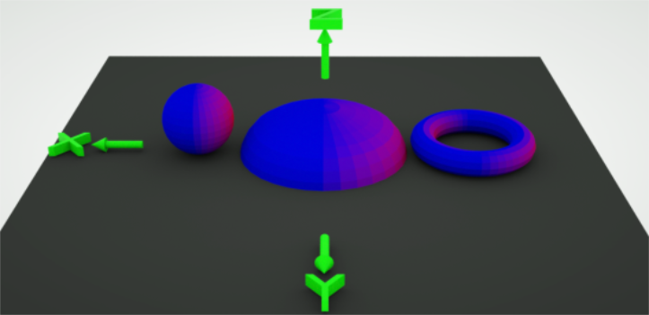
Figure 5: Skew factor = 1; Direction x = 1
Normal vs. Vector 180deg - OctaneRender® calculates the falloff from the angle between the Surface Normal and the specified direction vector, maxing out at 180 degrees. This provides a wider color range from the minimum to the maximum values, and maintains the effect of the color range according to the Falloff Direction parameter.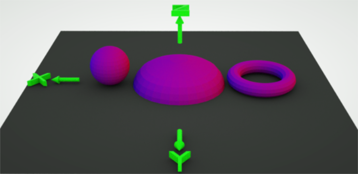
Figure 6: Skew factor = 1; Direction x = 1
![]()
Figure 7: Falloff Map parameters
Minimum Value - The visible material on the surface facing the camera. A value of 0 displays the material connected to Material pin 2, and a value of 1 displays the material connected to Material pin 1.
Maximum Value - Determines what material displays towards the grazing angles. A value of 0 displays the material connected to Material pin 2, and a value of 1 displays the material connected to Material pin 1.
Falloff Skew Factor - Balances the Normal and Grazing angles' influence. Low values result in stronger Grazing angle influence - any textures that the Maximum Value controls cover more surface. High values result in stronger Normal angle influence - any textures that the Minimum Value controls cover more surface.
In the figure below, a red Diffuse materialUsed for dull, non-reflecting materials or mesh emitters. connects to the Mix material's first Material pin, and a white DiffuseAmount of diffusion, or the reflection of light photons at different angles from an uneven or granular surface. Used for dull, non-reflecting materials or mesh emitters. material connects to the second Material pin. The Falloff map then connects to the Mix material's Amount pin.
A value of 0.1 leads to almost complete coverage by the grazing value regardless of viewing angle, whereas a value of 15 leads to almost complete coverage by the Normal value. This parameter's default setting is 6.
While the index value on GlossyThe measure of how well light is reflected from a surface in the specular direction, the amount and way in which the light is spread around the specular direction, and the change in specular reflection as the specular angle changes. Used for shiny materials such as plastics or metals. and SpecularAmount of specular reflection, or the mirror-like reflection of light photons at the same angle. Used for transparent materials such as glass and water. nodes corresponds to a real-world Index of Refraction (IOR) value on dielectric materials like plastic and glass (OctaneRender® doesn't yet support metals and Bezier curves), the Falloff node works differently because of this Falloff Skew Factor. If set to 1, then the value is proportional to the angle between the Normal and the Camera Ray. For example, if view angle is 45°, then the value is 0.5. If the value is larger than 1, then it applies a power curve to the angle. If the value is smaller than 1, then it inverts the skew factor, and mirrors the power curve.
falloff ≥ 1 : y = 1 – (1 – x) (1 / falloff )
This is used by the Normal vs. Vector 90deg and Normal vs. Vector 180deg modes. For most materials, the Fresnel effect (the default mode) is often correct, while Falloff Direction applies for exceptional cases, which can adjust relative to the camera. Changing the object rotation will not change the Falloff Direction orientation.
You can approximate the behavior of glass with a Skew Factor of 8.0 and a Normal value of 0.034.
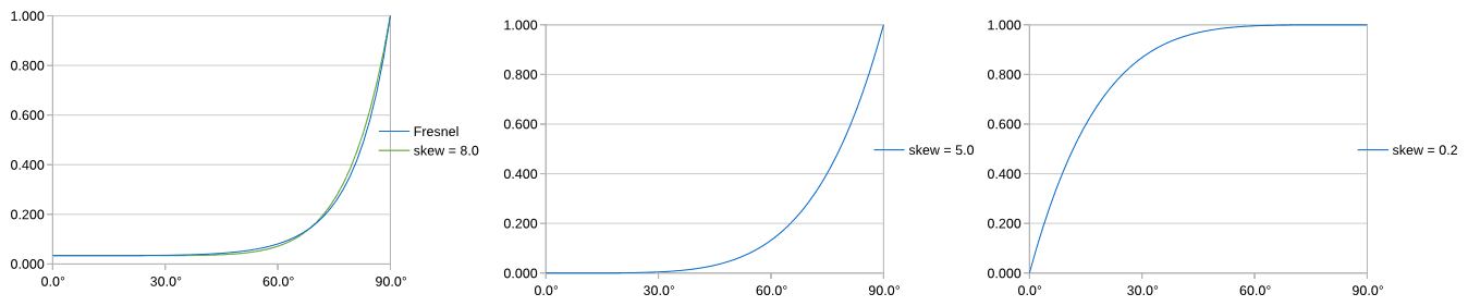
Figure 8: Falloff Direction curves
You can also use the Falloff Map for other things, like the input for glass opacity. Falloff is useful for car shaders, water shaders, and fabrics like velvet. It is also useful for some metals to simulate some coating effects.
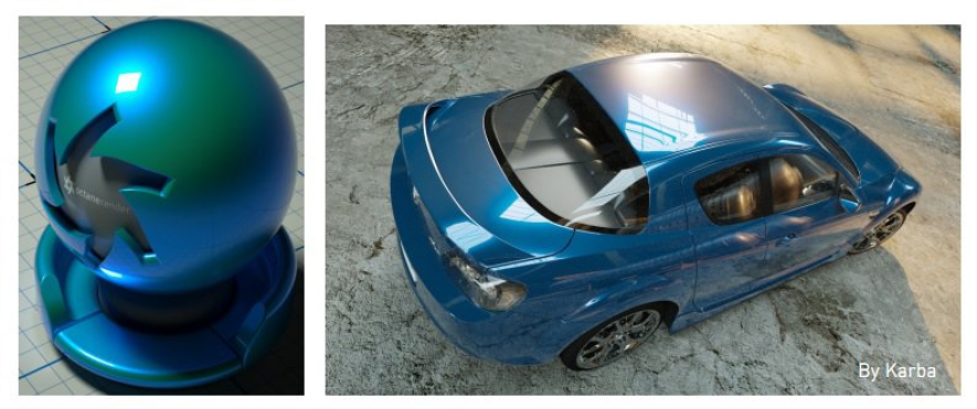
Figure 9: Car shader example