The OSL Camera node is a scriptable node. You can create custom camera types for any purpose (such as VRImmersively engaging and experiencing depth perception in a three dimensional scene through stereo vision goggles and head-mounted displays. warping) with OSL (Open Shader LanguageA shading language developed by Sony Pictures Imageworks. There are multiple render engines that utilize OSL as it is particularly suited for physically-based renderers.) scripts. It is a flexible camera used to match the rendering to the existing footage. One OSL Camera is one OSL compilation unit, which contains only one shader, so it has one output attribute pin that connects to the Camera input pin of a Render Target node. OSL is a standard created by Sony Imageworks. To learn about the generic OSL standard, information is provided from the OSL Readme and PDF documentation.
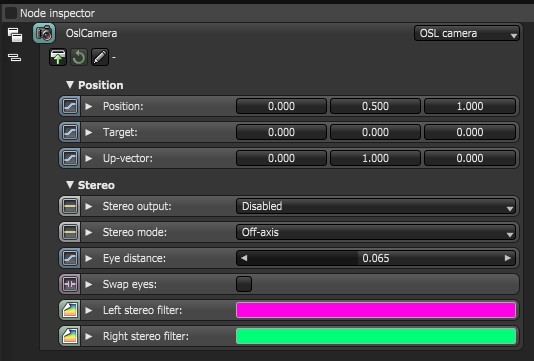
The inherent attributes of an OSL Camera node includes its position, target, up-vector (orientation) and stereo-related parameters (Figure 1). This means the moment you invoke an OSL Camera node, it supports Viewport controls, camera motion blur, and stereo rendering.
Figure 1: The inherent attributes of the OSL Camera node
The customized OSL script is written into the OSL Camera node to create custom camera types. To edit the script, click on the Pencil icon to go to the script editor window. If the script exists as an external OSL file, insert the OSL file into the node through the Load icon. You can edit any existing file already used within an OSL Camera node. To refresh the file and use the edits, click the Reload icon.
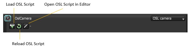
Figure 2: OSL script icons
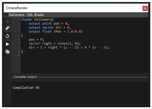
Figure 3: The script editor window showing the initial script of the OSL Camera node
When you invoke an OSL Camera node in OctaneRender’s node system, the node is provided with an initial OSL script (Figure 5):
Shader OslCamera (output point pos = 0,output vector dir = 0,output float tMax = 1.0/0.0){pos = P;vector right = cross (I, N);dir = I + right*(u-.5) + N*(v-.5);}
The initial script’s declaration component includes the three required outputs presented as variables with output types point, vector, and float, respectively. Each OSL I/O type corresponds to an OctaneRender® attribute:
For a list of OSL variable declaration input/output types in the OSL Specification that OctaneRender® supports, refer to the Appendix topic in this manual on OSL Implementation in OctaneRender®.
The three required output variables in the initial script’s declaration represents a camera ray’s position, direction, and maximal depth. The initial script’s function body then initializes the position and orientation of the OSL Camera shader using OSL global variables P, I, and N, which defines any standard camera’s eye, direction, and up vectors, respectively. To further control the position and orientation of the camera shader, you have two options:
You can create any camera type by customizing the script. Depending on the custom script, the resulting OSL shader may have more input type variables that appear as additional input pins on the OSL Camera node that represents it.
The camera shader has three outputs representing a ray (note that the names are arbitrary):
point pos = Ray position:
This is often set to P, but it may be set to other points to implement depth of fieldThe distance between the nearest and farthest objects in a scene that appear acceptably sharp in an image. Although a lens can precisely focus at only one distance at a time, the decrease in sharpness is gradual on each side of the focused distance, so that within the DOF, the unsharpness is imperceptible under normal viewing conditions. source: wikipedia (https://en.wikipedia.org/wiki/Depth_of_field), or a near clipping plane.
vector dir = Ray direction:
The render engine will take care of normalizing this vector if needed.
float tMax = Maximum ray tracing depth:
Measured along the direction of dir. May be used to implement a far clipping plane.
Set to 1.0/0.0 (infinity) to disable far clipping.
If tMax is 0, or if dir has 0 length, the returned ray is considered invalid, and the renderer will not perform any path tracing for this sample.
Like other camera types, OSL Camera nodes have static input pins that define the camera's position and orientation. It is not mandatory for your camera shader to use this position, but if it does, your camera supports motion blur and stereo rendering.
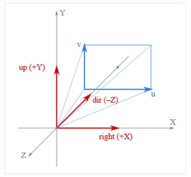
Figure 4: Camera position coordinates
Within camera shaders, the camera's position and orientation is available by the standard global variables defined by OSL:
point P: Camera position
vector I: Camera direction (sometimes called *forward*)
normal N: vector, perpendicular to I
float u, float v: Coordinates on the film plane, mapped to the unit square. (0, 0) is at the bottom-left corner. These coordinates can be fetched via getattribute("hit:uv", uv) and via the UV projection node.
Alternatively, the camera position is also available via the camera coordinate space. This is an orthonormal coordinate space. Without transform the camera is looking along the -Z axis with the +Y axis as up-vector, i.e. the axes are defined as:
+X: Right vector
+Y: Up vector
–Z: Camera direction
You can create your own custom camera using an OSL Camera node. As a starting point, below is a basic OSL implementation of a Thin Lens camera:
shader OslCamera(
float FocalLength = 1 [[ float min = 0.1, float max = 1000, float sliderexponent = 4]],output point pos = 0,output vector dir = 0,output float tMax = 1.0/0.0)
{
float pa;int res[2];getattribute("camera:pixelaspect", pa);getattribute("camera:resolution", res);float u1 = 2 * (u - .5);float v1 = 2 * (v - .5) * pa * res[1] / res[0];pos = P;vector right = cross(I, N);dir = 2*FocalLength * I + v1 * N + u1 * right;dir = transform("camera", "world", dir);
}
For a list of OSL variable declaration input/output types in the OSL Specification that OctaneRender® supports, refer to the Appendix topic on OSL Implementation in OctaneRender®. To learn more about scripting within OctaneRender® using the Open Shader Language, refer to The Octane OSL Guide.