The GlossyThe measure of how well light is reflected from a surface in the specular direction, the amount and way in which the light is spread around the specular direction, and the change in specular reflection as the specular angle changes. Used for shiny materials such as plastics or metals. material is used for shiny materials such as plastics or metals.
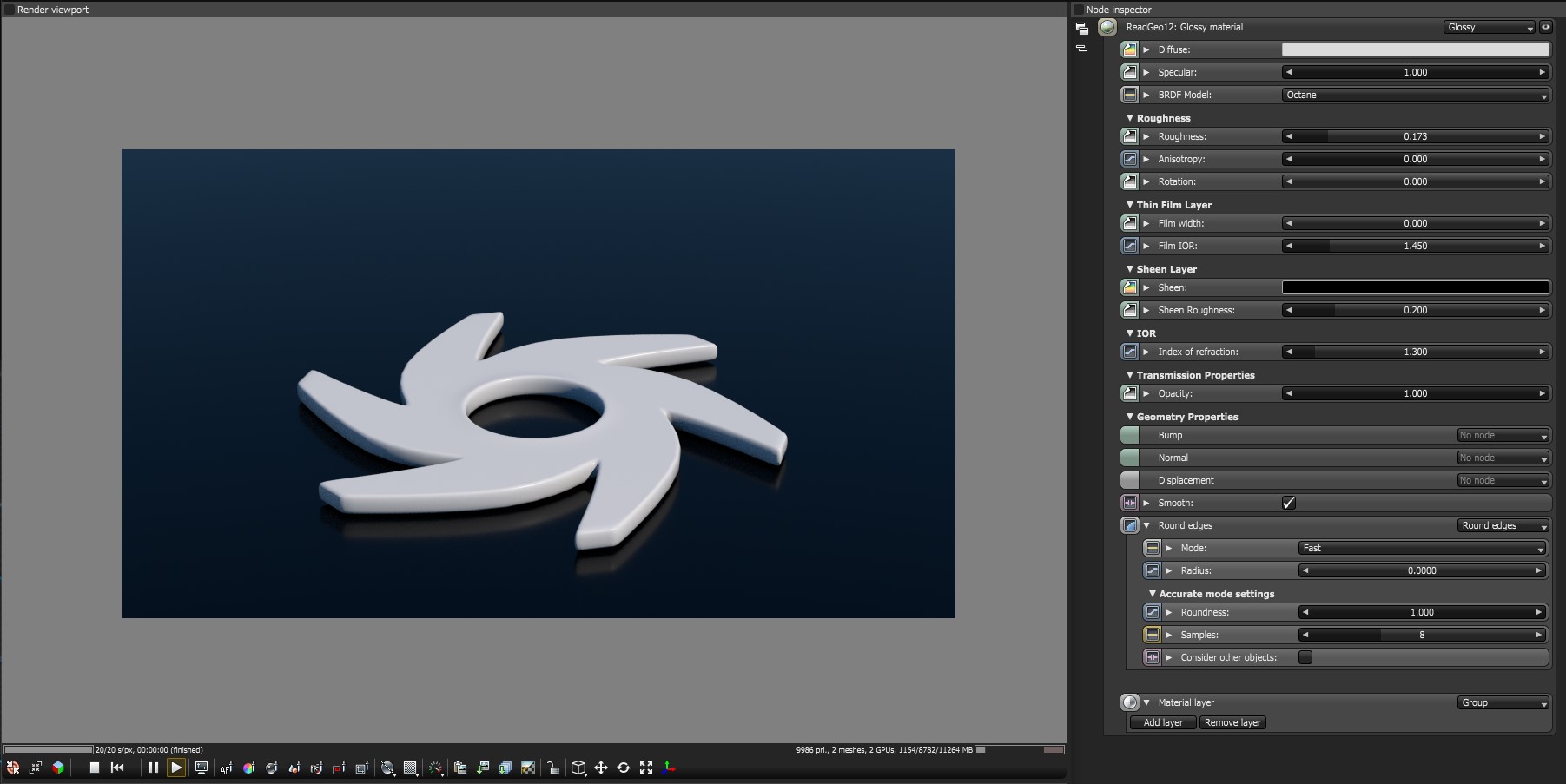
Figure 1: The Octane Glossy MaterialThe representation of the surface or volume properties of an object.
Glossy Material Parameters
DiffuseAmount of diffusion, or the reflection of light photons at different angles from an uneven or granular surface. Used for dull, non-reflecting materials or mesh emitters. - The Diffuse parameter gives the material its color. In computer graphics this is also referred to as “Base Color” or “Albedo”. Diffuse color can be can set using a value or by connecting a texture (procedural or image-based).
SpecularAmount of specular reflection, or the mirror-like reflection of light photons at the same angle. Used for transparent materials such as glass and water. - The Specularity parameter determines the intensity of specular reflections that appear on the surface. Specular reflections are reflections of light sources on a surface. The specular input accepts color, values, or textures. In most cases, specular highlights are white or colorless. However, to simulate metallic surfaces, the specular color should be tinted using a color similar to the diffuse parameter. Think of the bright yellow-orange highlights seen on the surface of a polished copper kettle. A glossy node with a black diffuse, 0 roughness and an index 0, will produce a perfect mirrors shown in Figure 2.
BRDF Model (Bidirectional Reflectance Distribution Function) - The BRDF is a function that determines the amount of light reflected from a material when light falls on it. For Glossy materials, there are four applicable BRDF Models to choose from. Each BRDF is effected by a specific geometric property - the microfacet distribution - of the surface which describes the microscopic shape (i.e. microfacet normals) of that surface and serves as a function to scale the brightness of the reflections in the BRDF. Refer to the topic on BRDF Models for more information.
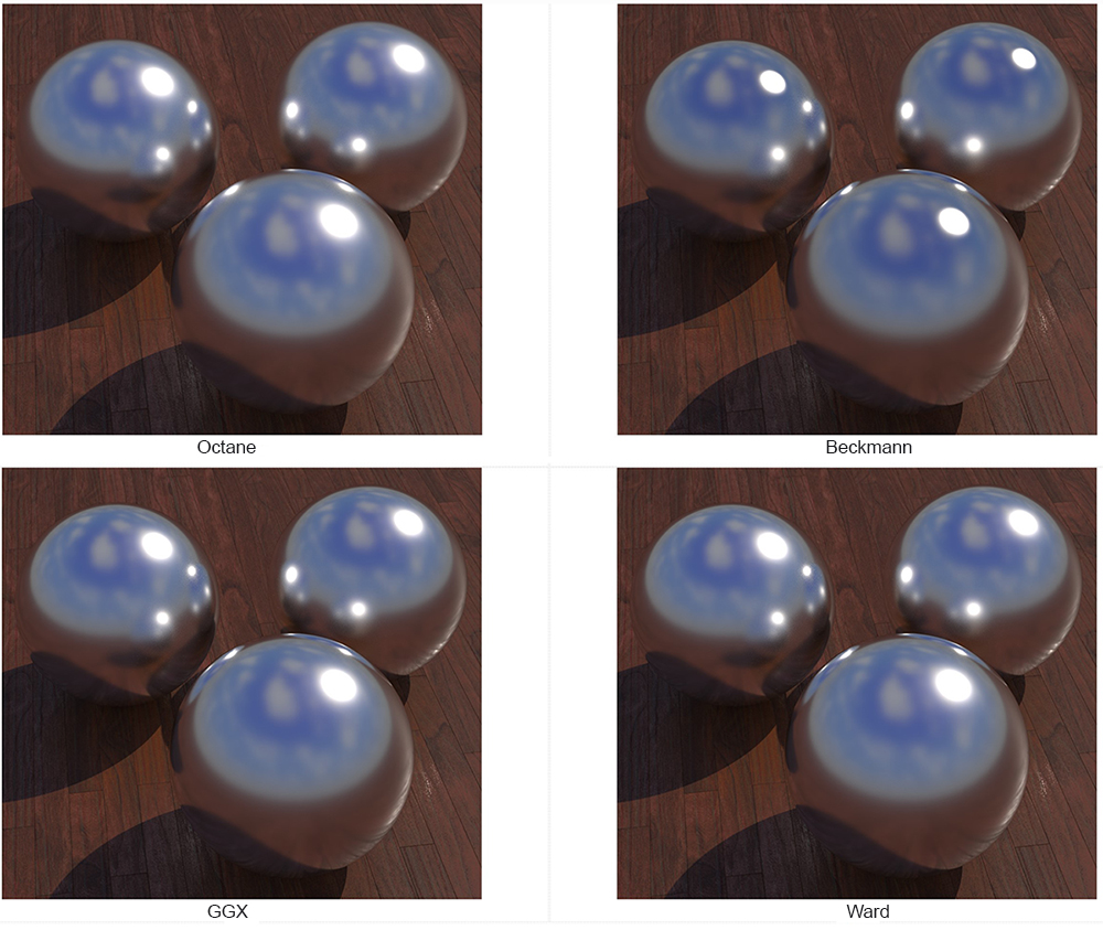
Figure 4: The four BRDF Models applicable to Glossy MaterialsA set of attributes or parameters that describe surface characteristics..
Roughness - The roughness parameter determines how much the specular reflection spreads across the surface. In CG terminology this is also referred to as “reflection blur”. A value of zero simulates a perfectly smooth reflective surface such as a mirror. Increasing the value simulates micro-facets in the surface which causes the reflective highlights to spread. For example to create the look of worn plastic you would increase the roughness value. This parameter accepts a value, color, or texture map (procedural or image-based).
Anisotropy - This controls the uniformity of the material’s reflectance. If the reflectance changes based on the orientation or the rotation of the surface it is said to be Anisotropic. And likewise, if the reflectance is uniform in all directions and does not change based on the orientation or the rotation of the surface, it is said to be Isotropic. By default this attribute is 0, and sets the metallic material initially as Isotropic. Non-0 values mean that the material will exhibit Anisotropic reflectance where -1 is horizontal and 1 is vertical.
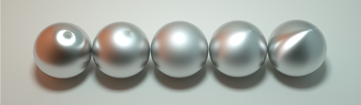
Figure 5: Anisotropic roughness exemplified in materials like brushed metal.
Rotation - This refers to the rotation of the anisotropic specular reflection channel.
Film Width - Film width simulates the look of a thin film of material on the surface. This is useful when you want to create an effect such as the rainbow colors that appear on the surface of an oil slick. Larger values increase the strength of the effect.
Film width simulates the look of a thin film of material on the surface. This is useful when you want to create an effect such as the rainbow colors that appear on the surface of an oil slick. Larger values increase the strength of the effect.
Film IOR - The Film IOR controls the Index of Refraction of the thin film, use this option to adjust the colors visible in the film.
Sheen - This is the sheen color of the material.
Sheen Roughness - This is the roughness channel for the sheen that is present on metallic and glossy materials.
Index of Refraction - Index of Refraction for glossy materials determines the strength of reflections on the surface based on the Fresnel law. The Fresnel law describes the physical properties of light as it is reflected off of a surface at grazing angles. If Index of Refraction is set to a value higher than 1, the reflection will be strongest on the parts of the surface that turn away from the viewer’s angle (grazing angles) while the reflection will appear weaker or less apparent on the parts of the surface that are perpendicular to the viewing angle. Because this is a physically based phenomena, the result is a more realistic looking surface. If Index of Refractions is set to a value lower than 1, then the fresnel effect is disabled and the reflection color will simply appear as a uniform color across the highlight. The color of the reflective highlight itself is determined by the color connected to the specular channel.
In the following examples, the six balls have roughness 0, 0.2, 0.4, 0.6, 0.8, 1.0 (left to right) and only the specular value and index of refraction have been modified for each rendered image (see Figure 3)
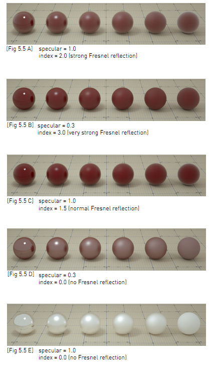
Figure 3: Spheres rendered using different settings for specular and index
Opacity - The Opacity parameter determines which parts of the surface are visible in the render. Dark values indicate transparent areas, light values determine opaque areas. Values in between light and dark create the look of semi transparent areas. You can lower the opacity value to fade the overall visibility of an object or use a texture map to vary the opacity across the surface. For example if you wanted to make a simple polygon plane look like a leaf you would connect a black and white image of the leaf’s silhouette to the opacity channel of the diffuse shader. When using an image texture map, set the data type to Alpha image (if the image has an alpha channel) or grayscale image(for black/white images) to load an image to set the transparency (use the Invert checkbox if necessary to adjust whether black or white regions are considered transparent).
Bump - The Bump parameter is used to create fine details on the material’s surface using a procedural or image texture. Typically a grayscale image texture is connected to this parameter, light areas of the texture give the appearance of protruding bumps, dark areas create the appearance of indentation. The strength of the bump map can be adjusted by setting the Power or GammaThe function or attribute used to code or decode luminance for common displays. The computer graphics industry has set a standard gamma setting of 2.2 making it the most common default for 3D modelling and rendering applications. values on the grayscale image texture node. These attributes are covered in more detail under the Texture Overview category.
Normal - The Normal parameter is also used to create the look of fine detail on the surface. A normal map is a special type of image texture that uses red, green, and blue color values to perturb the normals of the surface at render time thus giving the appearance of added detail. They can be more accurate than bump maps but require specific software, such as ZBrush, Mudbox, Substance designer, Xnormal, or others to generate. The Normal channel should be set to the image data type to load a full color normal map.
DisplacementThe process of utilizing a 2D texture map to generate 3D surface relief. As opposed to bump and normal mapping, Displacement mapping does not only provide the illusion of depth but it effectively displaces the actual geometric position of points over the textured surface. - The Displacement parameter adjusts the height of the vertices of a surface at render time using a texture map. Displacement maps differs from Bump or Normal maps in that the geometry is altered by the texture as opposed to just creating the appearance of detail. Displacement mapping is more computationally expensive than using a bump or normal map but the results can be more realistic especially along the silhouette of the surface. Displacement mapping is covered in more detail under the Texture Overview category.
Smooth - The Smooth parameter is a boolean (meaning that it is a toggle that turns the feature on or off) which smooths the transition between surface normals. If this option is disabled the edges between the polygons of the surface will be sharp giving the surface a faceted look.
Rounded EdgesThe Rounded Edges parameter bevels the edges of the surface at render time automatically without the need to alter or subdivide the geometry. Using this option can enhance the realism of objects by eliminating overly sharp edges. The value refers to the radius of the rounded edge. Higher values for this setting produce rounder edges.
Material Layer - Adds a Material Layer above the base material. See the Material Layers topic in this manual for more details.