Whilst IBL and daylight modes are the preferred methods for illuminating outdoor scenes, for indoor scenes you will need to create emitter geometry. This can either be done by modelling a simply part to be an emitter, or loading the predefined emitter part (called “Octane Inventor Emitter.ipt” copied into “C:\ProgramData\Autodesk\Application\Plugins\OctaneRender for Inventor” by the installer.
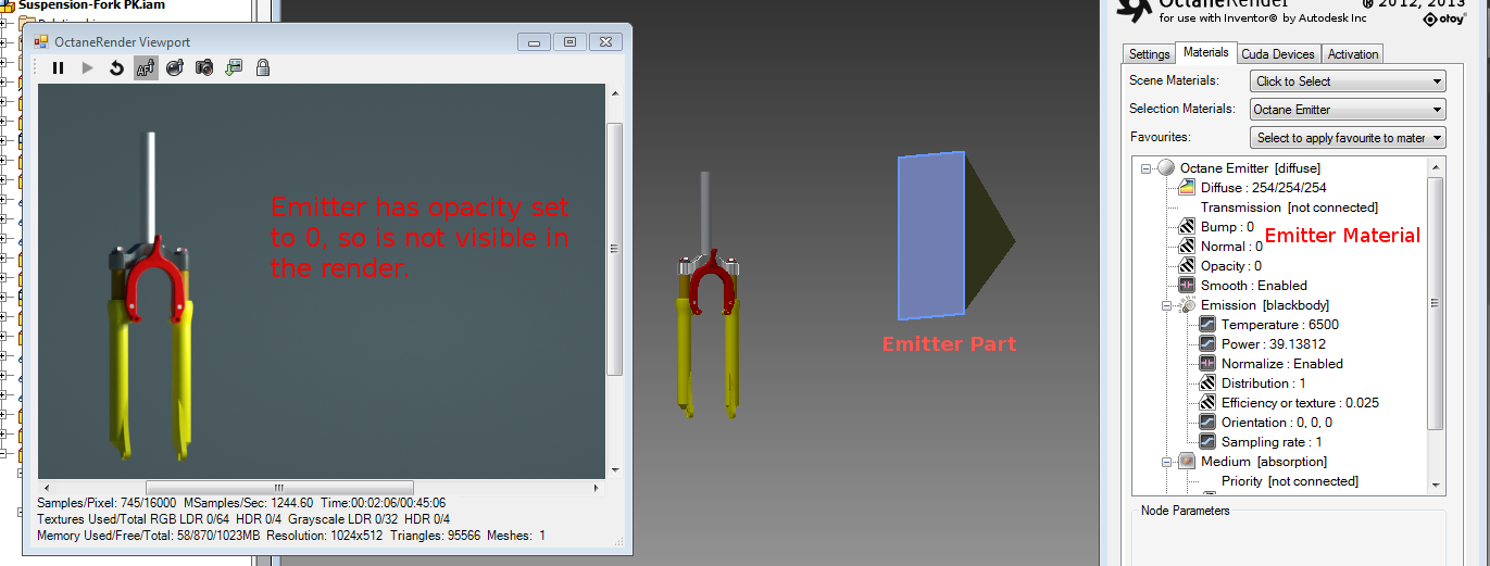
For the above emitter, to select the Octane emitter material, edit the emitter part, or pick with the Viewport MaterialThe representation of the surface or volume properties of an object. Picker. The Octane Emitter material can have the opacity set to 0 (to make the emitter invisible to the camera), or set to > 0 (ie. 0.1) to make it visible.
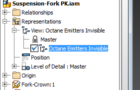
All Octane emitter parts can be set to invisible for a specific Inventor view, so that they can be removed from the scene for analytical purposes.
Any emitters in your scene should be as low-polygon as possible (ie. not high density meshes).
IESAn IES light is the lighting information representing the real-world lighting values for specific light fixtures. For more information, visit http://www.ies.org/lighting/. Lighting
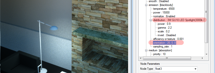
It is highly recommended that all emitter materials be setup with an IES distribution. This allows the emission of light to be distributed to certain parts of the scene. IES files can be downloaded from various sources.
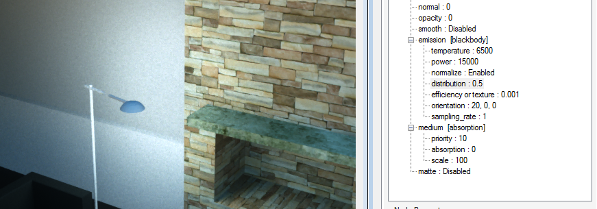
With no IES file plugged into the “distribution” pin, the light spreads equality in all directions from the lamp.
With an IES distribution file plugged into the “distribution” pin (as an “image” node), the light now only goes down. The direction of light can be controlled by the “orientation” pins.