One of the features that makes Octane so powerful is the ability to handle a very large number of instances. Generating instances is usually done via third party tools which generate scatter data that can be imported into Octane.
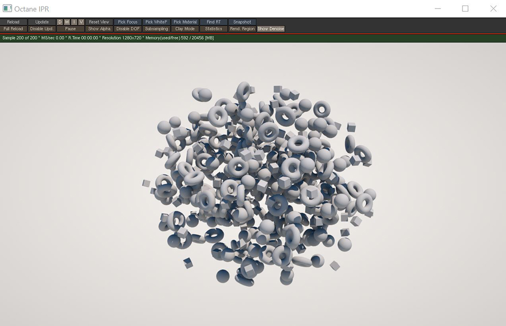
The Scatter on volume node generates an arbitrary number of instances according to various patterns and distributes them in a volume (figure 1).
Figure 1: The Scatter On Volume node used to scatter instances in a spherical volume shape
The Scatter on Volume node should be added to an Octane VOP NET in the MAT network. A Geometry node should be added to the OBJ network as the scatter object. It does not matter what is in this Geometry node as long as it contains a node that can have the Display flag enabled. The Octane Object Spare Parameters should be added to the scatter object node (figure 2).

Figure 2: Adding the Object Spare Parameters to the scatter Geometry node
The Scatter tab in the Object Spare Parameters is where all the connections are made for the scatter system to function properly (figure 3). The Scatter VOP node parameter should point to the Scatter on Volume node in the MAT network. The Scattered Object 1-4 parameter should point towards the objects to be scattered.
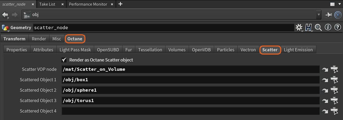
Figure 3: The Scatter parameters required for Scatter on Volume to function properly
Object Selection Method - The method for scattering the connected objects. The available scattering methods are Sequential, Random, and Selection Map.
Object Selection Seed - Seed value used to randomize the selection of source objects.
Dimension Determines the number of instances along each dimension (x,y,z).
Offsets - Determines the offset between the instances along each dimension (x,y,z).
Shape - Determines the shape of the volume in which the objects are scattered.
Culling Min - All instances in areas of the map that have a value below this threshold are removed.
Culling Max - All instances in areas of the map that have a value above this threshold are removed.
Orientation Priority - If the Up and Front Vector are not orthogonal, this parameter determines which one has priority.
Up Direction Mode - Selects between the use of a reference direction or a reference point. Reference point allows for finer (more localized) control over the orientation of the scatter objects.
Reference Up Direction - When Up mode is set to Direction, the reference up vector will point in this direction.
Reference Up Point - When Up mode is set to Point, the reference up vector will point towards this location.
Front Direction Mode - Selects between the use of a reference direction or a reference point for the front direction of the scattered objects.
Reference Front Direction - When Front mode is set to Direction, the reference front vector will point in this direction.
Reference Front Point - When Front mode is set to Point, the reference front vector will point towards this location.
Rotation Mode - Determines how the rotation parameters will affect the instanced geometry.
Rotation Min - Specifies the minimum rotation value for the instances.
Rotation Max - Specifies the maximum rotation value for the instances.
Rotation Step - When the Rotation mode is set to Random or Map and this parameter is non-zero, the values will be aliased to the nearest step.
Scale Mode - Determines how the scale parameters will affect the instanced geometry.
Scale Min - Specifies the minimum scale value for the instances.
Scale Max - Specifies the maximum scale value for the instances.
Scale Step - When the Scale mode is set to Random or Map and this parameter is non-zero, the values will be aliased to the nearest step.
Translation Mode - Determines how the translation parameters will affect the instanced geometry.
Translation Min - Specifies the minimum translation value for the instances.
Translation Max - Specifies the maximum translation value for the instances.
Translation Step - When the Translation mode is set to Random or Map and this parameter is non-zero, the values will be aliased to the nearest step.