One of the features that makes Octane so powerful is the ability to handle a very large number of instances. Generating instances is usually done via third party tools which generate scatter data that can be imported into Octane.
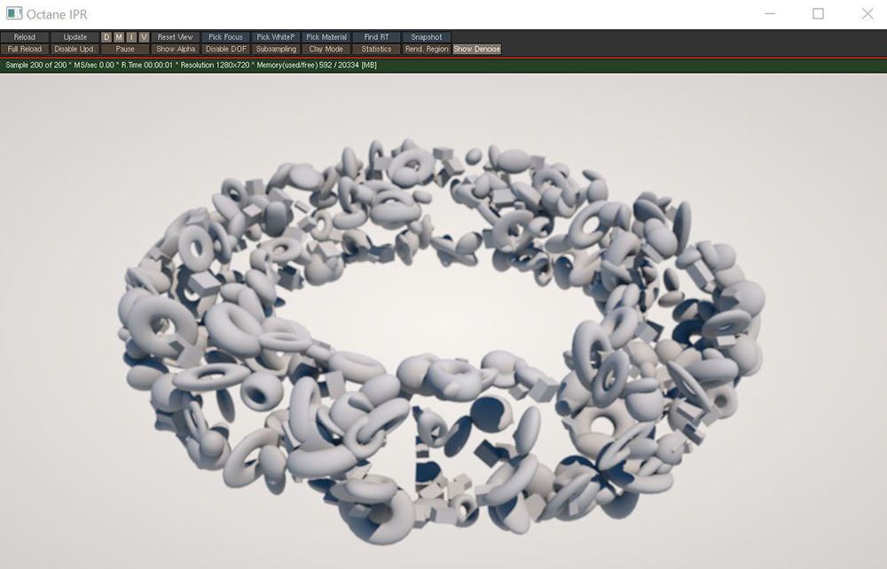
The Scatter on Surface node generates an arbitrary number of instances according to various patterns and distributes them across the area of a surface (figure 1).
Figure 1: The Scatter On Surface node used to scatter instances across a torus shape
The Scatter on Surface node should be added to an Octane VOP NET in the MAT network. A Geometry node should be added to the OBJ network and the geometry in this node will be used as the scattering surface. The Octane Object Spare Parameters should be added to the geometry node containing the scattering surface (figure 2).

Figure 2: Adding the Object Spare Parameters to the scatter Geometry node
The Scatter tab in the Object Spare Parameters is where all the connections are made for the scatter system to function properly (figure 3). The Scatter VOP node parameter should point to the Scatter on Surface node in the MAT network. The Scattered Object 1-4 parameter should point towards the objects to be scattered.
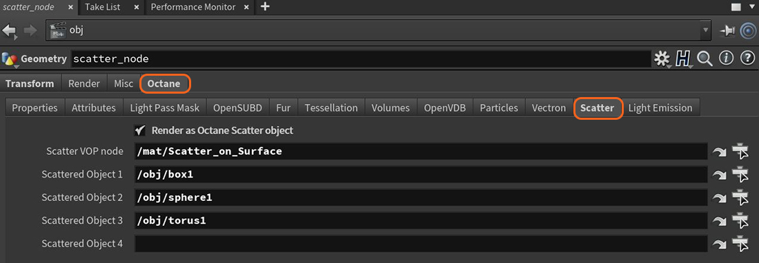
Figure 3: The Scatter parameters required for Scatter on Surface to function properly
Object Selection Method - The method for scattering the connected objects. The available scattering methods are Sequential, Random, and Selection Map.
Object Selection Seed - Seed value used to randomize the selection of source objects.
Distribution on Surfaces- The method used to distribute the instances on the scatter surface.
Distribution on Particles - This option will distribute the instanced on particles.
Distribution on Hair - Allows for instances to be distributed along hair strands
Position on Edge - When scattering on edges, this defines the position of instances along the edge.
Spacing on Edges - When scattering on edges, this defines the spacing between instances along the edge.
Poisson Disk Sampling - When randomly scattering on the surface by area or relative density, this option distributes the instances so that no two instances are too close to each other.
Position on Hair - When scattering on hair strands, this defines the position of the instances along the hair.
Spacing on Hair - When scattering on hair strands, this defines the spacing between instances.
Seed - The global seed used to randomize instance placement.
Instances - When the Distribution Method is set to Surface Area or Relative Density, this parameter determines the total number of instances to scatter across the surface.
Culling Min - All instances in areas of the map that have a value below this threshold are removed.
Culling Max - All instances in areas of the map that have a value above this threshold are removed.
Culling Angle Low - All instances on surfaces with a normal below this threshold in relation to the reference up vector are removed.
Culling Angle High - All instances on surfaces with a normal above this threshold in relation to the reference up vector are removed.
Smooth Normals - Determines whether there should be smoothing applied across the surface of the instances.
Normal Align - Blend factor between the reference up direction and the default normal of the instance. Values closer to 0 align the instance with the reference up direction and values towards 1 align with the default normal.
Orientation Priority - If the Up and Front Vector are not orthogonal, this parameter determines which one has priority.
Up Direction Mode - Selects between the use of a reference direction or a reference point. Reference point allows for finer (more localized) control over the orientation of the scatter objects.
Reference Up Direction - When Up mode is set to Direction, the reference up vector will point in this direction.
Reference Up Point - When Up mode is set to Point, the reference up vector will point towards this location.
Front Direction Mode - Selects between the use of a reference direction or a reference point for the front direction of the scattered objects.
Reference Front Direction - When Front mode is set to Direction, the reference front vector will point in this direction.
Reference Front Point - When Front mode is set to Point, the reference front vector will point towards this location.
Rotation Mode - Determines how the rotation parameters will affect the instanced geometry.
Rotation Min - Specifies the minimum rotation value for the instances.
Rotation Max - Specifies the maximum rotation value for the instances.
Rotation Step - When the Rotation mode is set to Random or Map and this parameter is non-zero, the values will be aliased to the nearest step.
Scale Mode - Determines how the scale parameters will affect the instanced geometry.
Scale Min - Specifies the minimum scale value for the instances.
Scale Max - Specifies the maximum scale value for the instances.
Scale Step - When the Scale mode is set to Random or Map and this parameter is non-zero, the values will be aliased to the nearest step.
Scale Map - The texture map used to associate each instance with a factor to control scale.
Translation Mode - Determines how the translation parameters will affect the instanced geometry.
Translation Min - Specifies the minimum translation value for the instances.
Translation Max - Specifies the maximum translation value for the instances.
Translation Step - When the Translation mode is set to Random or Map and this parameter is non-zero, the values will be aliased to the nearest step.