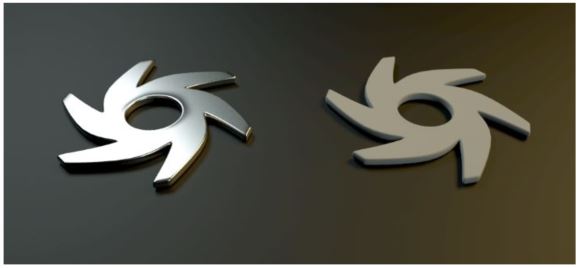
This material type creates more realistic metal. The Metallic material is clearly distinguished from the GlossyThe measure of how well light is reflected from a surface in the specular direction, the amount and way in which the light is spread around the specular direction, and the change in specular reflection as the specular angle changes. Used for shiny materials such as plastics or metals. material both in terms of the SpecularAmount of specular reflection, or the mirror-like reflection of light photons at the same angle. Used for transparent materials such as glass and water. and IOR parameters (Figure 1).
Figure 1: A comparison of the Metallic material (left) with a default Glossy materialUsed for shiny materials such as plastics or metals. (right)
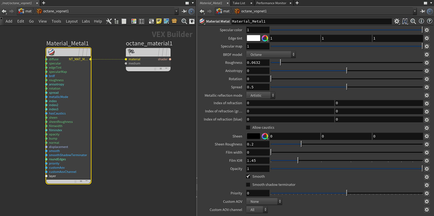
Figure 2: The Octane Metallic material parameters
DiffuseAmount of diffusion, or the reflection of light photons at different angles from an uneven or granular surface. Used for dull, non-reflecting materials or mesh emitters. Input - The Diffuse parameter gives the material its color. In computer graphics, this is also referred to as base color or albedo. You can set Diffuse color using the color picker or by connecting a Texture (Procedural or Image-based).
Specular Color - Determines the intensity of Specular reflections that appear on the surface. Specular reflections are reflections of light sources on the surface. The Specular input accepts color values and textures. In most cases, specular highlights are white or colorless. However, to simulate metallic surfaces, the Specular color should be a color similar to the Diffuse parameter. Think of the bright yellow-orange highlights seen on the surface of a polished copper kettle.
Edge Tint - The edge of the metal's color, only used in artistic and IOR+color mode.
Specular Map - Mixes the Diffuse and Specular components.
BRDF Model - The BRDF (Bidirectional Reflectance Distribution Function) determines the amount of light that a material reflects when light falls on it. For Glossy materials, you can choose from six BRDF models. Specific geometric properties (the micro-facet distribution) of the surface affects each BRDF, which describes the surface's microscopic shape (i.e. micro-facet normals) and scales the brightness of the BRDF's reflections. Refer to the topic on BRDF Models in the Standalone documentation for more information.
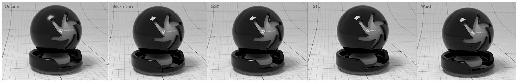
Figure 3: Examples of the BRDF types
Roughness - Determines how much the specular reflection spreads across the surface. In CG terminology, this is referred to as reflection blur. A value of 0 simulates a smooth reflective surface, such as a mirror. Increasing the value simulates microfacets in the surface, which causes the reflective highlights to spread. For example, to create the look of worn plastic, increase the Roughness value. This parameter accepts a value or Texture map (Procedural or Image-based).
Anisotropy - This attribute adjusts the amount of change in a surface's reflectance, depending on viewing direction.
Rotation - This attribute controls the orientation of the Anisotropy effect.
Spread - Determines the tail spread for the specualr BSDF (Bidirectional ScatteringDefines how fast light gets scattered when traveling through the medium. Distribution Function) model of the specular layer.
Metallic Reflection Mode - This attribute, along with the IOR attributes, provide options for controlling the Index of Refraction across a surface.
IOR attributes associated with the Metallic Refl. Modes. Complex-valued Index Of Refraction controlling the Metallic reflection's Fresnel effect, where n = the refractive index, and k = the extinction coefficient. For the following parameters, the left field is the value for "n" and the right field is the value for "k."
Allow Caustics - If enabled, the photon tracing kernel will create caustics for light reflecting or transmitting through the object.
Sheen - This attribute provides control for applying a soft luster to a surface.
Sheen Roughness - Determines how much the sheen spreads across the surface, similar to the Roughness control for the specular characteristics.
Film Width - This controls the thickness of the optical, thin film on the material. This is useful in creating rainbow or oil slick effects.
Film IOR - This controls the Index Of Refraction of the thin film.
Opacity - Determines what parts of the surface are visible in the render. Dark values indicate transparent areas, and light values determine opaque areas. Values in between light and dark create the look of semi-transparent areas. You can lower the Opacity value to fade the overall visibility of an object, or use a Texture map to vary the opacity across the surface. For example, if you wanted to make a simple polygon plane look like a leaf, you would connect a black-and-white image of the leaf’s silhouette to the Opacity channel of the Diffuse shader.
Bump Input - Creates fine details on the material’s surface using a Procedural or Image texture. When you connect a grayscale texture to this parameter, light areas of the texture give the appearance of protruding bumps, and dark areas create the appearance of indentation. You can adjust the strength of the Bump map by adjusting the Power or GammaThe function or attribute used to code or decode luminance for common displays. The computer graphics industry has set a standard gamma setting of 2.2 making it the most common default for 3D modelling and rendering applications. values on the Image texture node. These attributes are covered in more detail under the Texture Overview category.
Normal Input - The Normal parameter also creates fine details on the surface. A Normal map is a special type of image texture that uses red, green, and blue color values to perturb the normals of the surface at render time, thus giving the appearance of added detail. They can be more accurate than Bump maps, but require specific software, such as ZBrush®, Mudbox®, Substance Designer, XnormalTM, or others to generate.
DisplacementThe process of utilizing a 2D texture map to generate 3D surface relief. As opposed to bump and normal mapping, Displacement mapping does not only provide the illusion of depth but it effectively displaces the actual geometric position of points over the textured surface. Input - Adjusts the height of the vertices of a surface at render time using a Texture map. Displacement maps differs from Bump or Normal maps in that the geometry is altered by the texture, as opposed to just creating the appearance of detail. Displacement mapping is more complex than using a Bump or Normal map, but the results can be more realistic, in particular along the surface's silhouette. Displacement mapping is covered in more detail under the Texture Overview category.
Smooth - The Smooth parameter smooths the transition between surface normals. If you disable this option, the edges between the polygons of the surface are sharp, giving the surface a faceted look.
Smooth Shadow Terminator - If enabled, self-intersecting shadows for low polygon objects is smoothed according to the polygon's curvature.
Round Edges Input - This creates a shader effect at render time that rounds the sharp edges of objects without modifying and reloading the geometry. Higher values will round the edges more. This is useful to bevel hard edges during render time, like when using low-polygon models. This node is located under the Procedurals section.
Priority - Used to resolve the ambiguity in overlapping surfaces, the surface priority control allows artists to control the order of preference for surfaces. A higher number suggests a higher priority for the surface material, which means it is preferred over a lower priority surface material if a ray enters a higher priority surface and then intersects a lower priority surface while inside the higher priority surface medium.
Custom AOV - Writes a mask to the specified custom AOV.
Custom AOV Channel - Determines whether the custom AOV is written to a specific color channel (R, G, or B) or to all the color channels.
Layer Input - Adds a MaterialThe representation of the surface or volume properties of an object. Layer above the base material. See the Material Layers topic in this manual for more details.