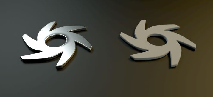
This material type is used to create more realistic metal. The Metallic MaterialThe representation of the surface or volume properties of an object. is clearly distinguished from the GlossyThe measure of how well light is reflected from a surface in the specular direction, the amount and way in which the light is spread around the specular direction, and the change in specular reflection as the specular angle changes. Used for shiny materials such as plastics or metals. material both in terms of the specular and IOR parameters (figure 1).
Figure 1: A comparison of the Metallic material (left) with a default Glossy materialUsed for shiny materials such as plastics or metals. (right).
The shader consists of numerous tabs that categorize the large set of options available for any particular shader type (figure 2). These categories of options are described below.
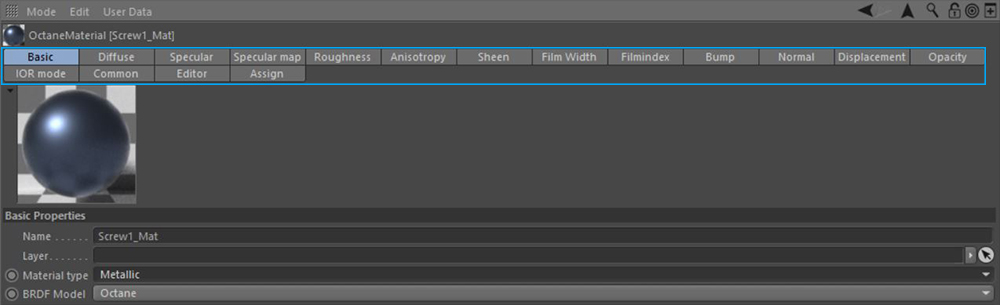
Figure 2: The Metallic shader's tabs categories.
This parameter does not work alone in the case of metallic materials. It works in conjunction with the SpecularAmount of specular reflection, or the mirror-like reflection of light photons at the same angle. Used for transparent materials such as glass and water. parameter. Coloring a metal is like painting a natural metal element, also called coating. To directly affect the perceived surface color of a Metallic material, adjust the Specular parameter's Color value instead. Additionally, the Specular Map parameter allows for mixing of the Diffuse and Specular components. That parameter is covered below.
Specular
This parameter is responsible for the direct surface color of a Metallic material. The Specular tab contains four options as described below.
Color
Sets the diffuse color.
Float
Creates a grayscale value. If the RGB color is zero, this float value creates black for 0 and white for 1. The float value also works the same in Roughness, Bump, Normal, Opacity and TransmissionA surface characteristic that determines if light may pass through a surface volume. channels.
Texture
Defines a texture for the diffuse channel. These textures can be any of the image or procedural texture types. If a texture is added here, both the Color and Float values are disabled.
Mix
This option mixes both the Color and the Texture type. Color is assigned to zero, and 1 indicates the Texture. Values between 0 and 1 mix these two.
Specular Map
This parameter is used to mix the Diffuse and Specular components (figure 3).
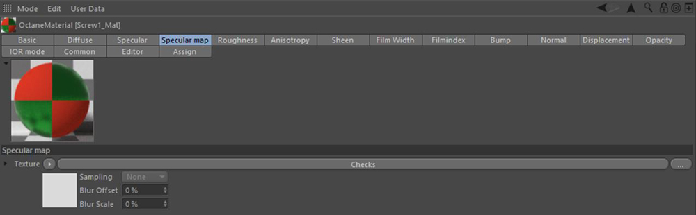
Figure 3: Mixing a red Diffuse Color value with a green Specular Color value using a Checks texture in the Specular Map parameter.
The following example illustrates a more complex mixing of the Diffuse and Specular components using the Specular Map component (figure 4).
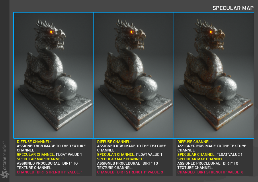
Figure 4: Creating a complex blend using the Specular Map component.
Roughness
The Roughness parameter determines how much the specular reflection spreads across the surface. In CG terminology this is also referred to as “reflection blur”. A value of zero simulates a perfectly smooth reflective surface such as a mirror. Increasing the value simulates microfacets in the surface which causes the reflective highlights to spread. For example to create the look of worn plastic you would increase the roughness value. This parameter accepts a value or texture map (procedural or image-based). In Octane's new BRDF models, the roughness parameter now produces more realistic results (figure 5). These BRDF types are set in the Basic tab from the BRDF Model dropbox.
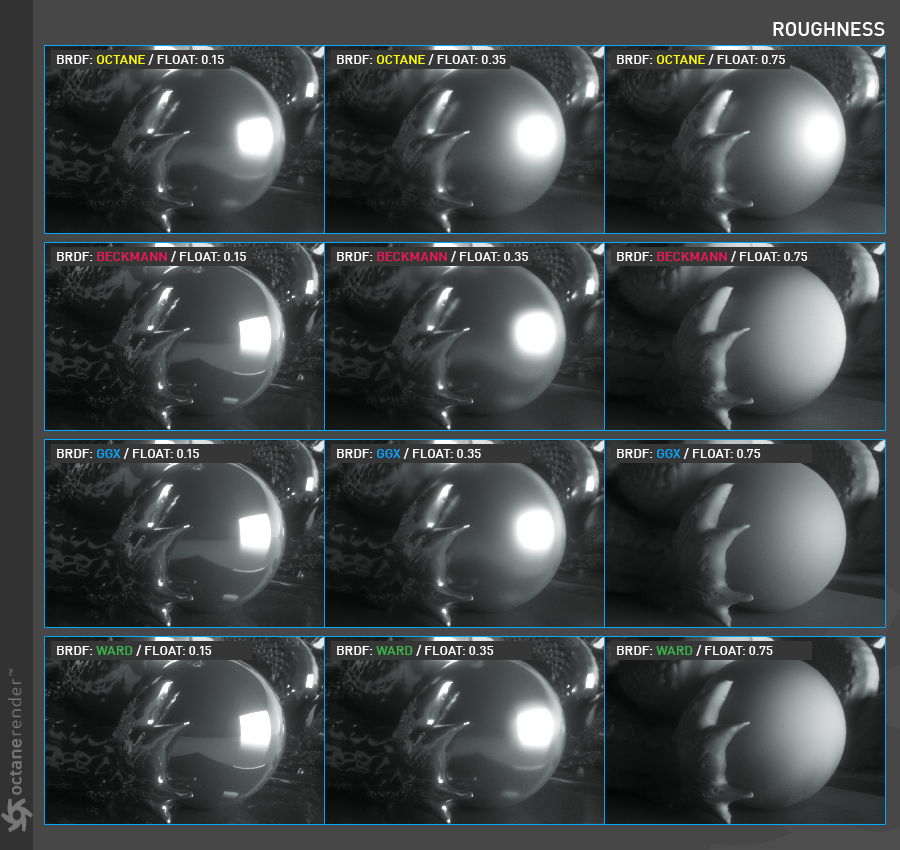
Figure 5: Comparison of the various BRDF types available in Octane.
Anisoptropy
Anisotropy is the reflection value changes by turning the surface around its normal. Examples of anisotropic surfaces include polished metal, human hair, fur and wood.
Anisotropy
Determines the amount of anisotropy applied to the surface. It can be a negative or positive value.
Rotation
Rotates the anisotropy by a texture. A wide variety of effects can be attained by turning the surface normals. Any texture image or procedural can be used, provided that it's a grayscale image. The following picture shows the anisotropy properties of different BRDF models. In this image the roughness value is fixed and a grayscale image texture is used for rotation (figure 6).
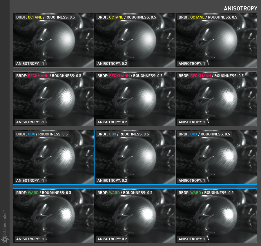
Figure 6: Using an image texture for the Rotation parameter.
Sheen
Used for simulating cloth and velvet or satin-like materials. It increases the reflectance for grazing angle with varying roughness. Less roughness means a sharper peak of sheen reflection around the grazing angle, higher roughness means a less sharp peak and a more spread out sheen reflection across the fabric surface (figure 7).
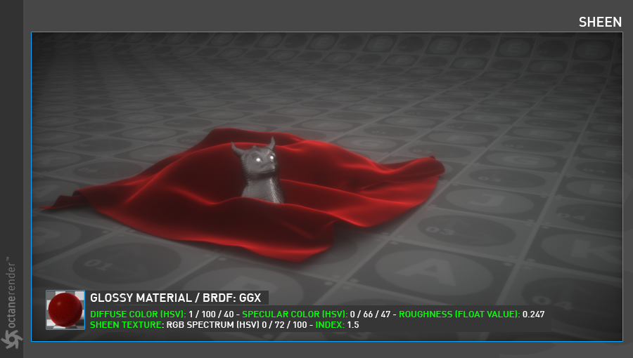
Figure 5: An example of the Sheen parameter applied to a Glossy material.
Film Width
Film width simulates the look of a thin film of material on the surface. This is useful when you want to create an effect such as the rainbow colors that appear on the surface of an oil slick. Larger values increase the strength of the effect.
Film Index
The Film IOR controls the Index of Refraction of the thin film, use this option to adjust the colors visible in the film.
Bump
The bump parameter is used to create fine details on the material’s surface using a procedural or image texture (figure 7). Typically a gray-scale texture is connected to this parameter, light areas of the texture give the appearance of protruding bumps, dark areas create the appearance of indentation. The strength of the bump map can be adjusted by setting the Power value on the Octane image texture node. These attributes are covered in more detail under the TexturesTextures are used to add details to a surface. Textures can be procedural or imported raster files. section.
Normal
The normal parameter is also used to create the look of fine detail on the surface. A normal map is a special type of image texture that uses red, green, and blue color values to perturb the normals of the surface at render time thus giving the appearance of added detail (figure 8). They can be more accurate than bump maps but require specific software, such as ZBrush, Mudbox, Substance designer, Xnormal, or others to generate.
The displacement parameter adjusts the height of the vertices of a surface at render time using an image texture map. Displacement maps differs from bump or normal maps in that the geometry is altered by the texture as opposed to just creating the appearance of detail (figure 9). Displacement mapping is more computationally expensive than using a bump or normal map but the results can be more realistic especially along the silhouette of the surface. Displacement will be described in more detail in the chapter Using Textures / Displacement.
Opacity
The opacity parameter determines which parts of the surface are visible in the render. Dark values indicate transparent areas, light values determine opaque areas (figure 10). Values in between light and dark create the look of semi transparent areas. You can lower the opacity value to fade the overall visibility of an object or use a texture map to vary the opacity across the surface. For example if you wanted to make a simple polygon plane look like a leaf you would connect a black and white image of the leaf’s silhouette to the opacity channel of the diffuse shader.
IOR Mode
This controls the complex IOR settings of the metallic material. By default metals use the Schlick approximation for the Fresnel effect. For a more precise falloff, a complex IOR can be entered (commonly known as n and k values). When a complex IOR is set up, the metallic color will get scaled so the brightness matches the Fresnel falloff for that IOR. The Metallic Reflection Mode parameter has three types: Artistic, IOR + Color, and RGB IOR.
Artistic
This mode uses only the Specular color. The values entered into the Index of refraction below have no impact. It is simple and ideal for non-realistic results (figure 6).
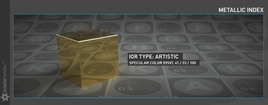
Figure 6: The Artistic mode.
IOR + Color
This mode uses "n and k" IOR values as along with the Specular color. "n" and "k" are actual index values that can be found on the web for various material types. Use the numeric field for "n" on the left and "k" on the right. Any color can still be specified in the Specular parameter (figure 7).
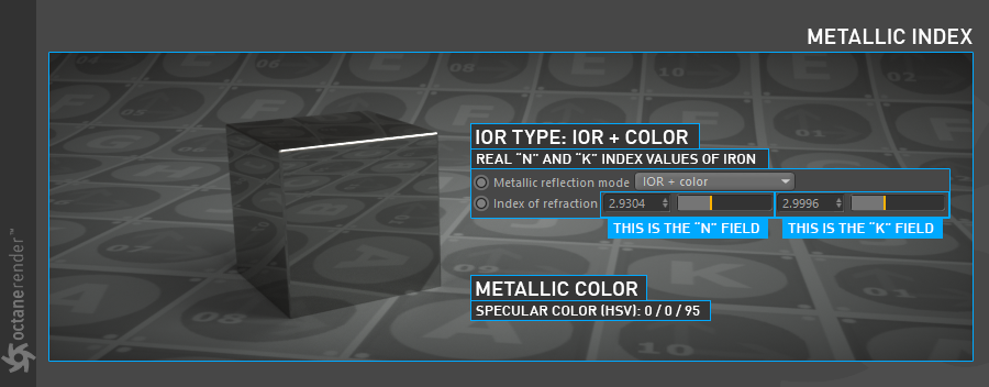
Figure 7: Adjusting the n and k values.
RGB IOR
This mode provides the most accurate results. Using the wavelengths of the visible spectrum, both color and index can be specified (Specular is disabled). Essentially, one column of values controls the IOR and the other column of values controls the color (figure 8). There is a complex interaction between the value sliders. It is recommended to simply experiment to get the desired result.
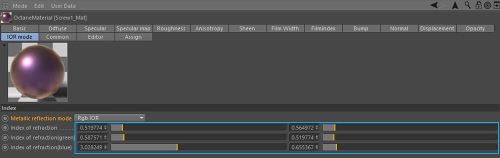
Figure 8: The RBG IOR sliders in the IOR mode tab.
Common
This parameter tab consists of several options.
Smooth
The Smooth parameter is a Boolean (meaning that it is a toggle that turns the feature on or off) which smooths the transition between surface normals. If this option is disabled the edges between the polygons of the surface will be sharp giving the surface a faceted look.
Affect Alpha
When using specular materials, this option shows the refractive parts of a material as alpha. For this parameter to function properly, the Alpha ChannelA greyscale image used to determine which areas of a texture map are opaque and which areas are transparent. setting needs to be active in the Kernel settings.
Rounded Edgess
The Rounded Edges parameter bevels the edges of the surface at render time automatically without the need to alter or subdivide the geometry. Using this option can enhance the realism of objects by eliminating overly sharp edges. The value refers to the radius of the rounded edge. Higher values for this setting produce rounder edges.
C4D Shader Resolution
Adjusts the Cinema 4D shader quality.
Vertex Map Resolution
This parameter works internally. The default value is recommended.
Editor
This tab consists of the classic Cinema 4D's material editor options. If you want to learn the details, you can look at the corresponding section in the Help file of Cinema 4D.
Assign
Displays which objects in a scene have the material assigned to them.