KernelsBy definition, this is the central or most important part of something. In Octane, the Kernels are the heart of the render engine. are very important part of the Octane Render. The kernel is what determines the rendering style of Octane. There are 4 different kernel modes: Directligting, Pathtracing, PMC and Infochannels. Each kernel mode has advantages and disadvantages. Each of them varies according to the structure of a scene, lighting, material and many other factors.
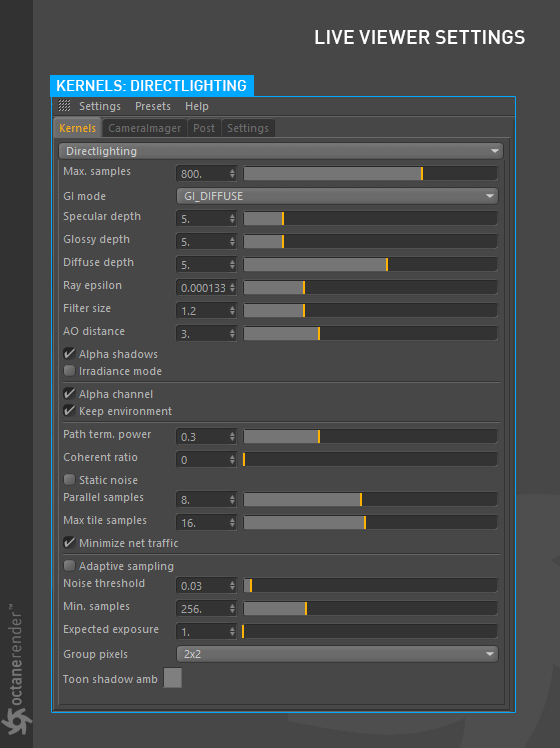
The Direct Lighting Kernel is generally used for faster preview rendering. It's not unbiased and will not yield photorealistic results, however because of its speed it can be the ideal choice for rendering animations or stills depending on purpose. The following picture shows the Directlighting settings (figure 1). Some of these settings are shared with the other kernel types.
Figure 1: The options for the Direct Lighting Kernel.
Max. Samples
Sets the maximum number of samples per pixel before the rendering process stops. The higher the number of samples per pixel, the cleaner the render (figure 2). There is no rule as to how many samples per pixel are required for a good render, it is subjective and may vary depending on the content and complexity of the scene being rendered.
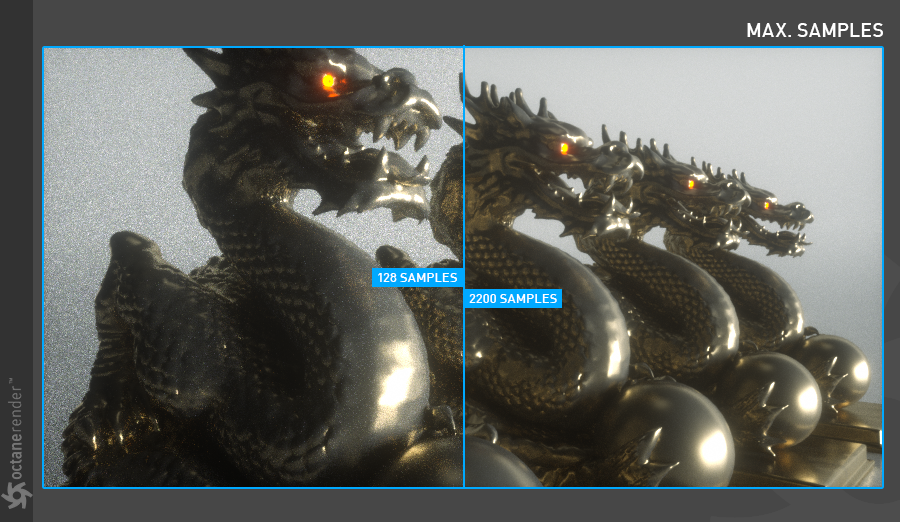
Figure 2: Max sample rate comparison.
GI Mode
This mode also has 3 sub-options (figure 3):
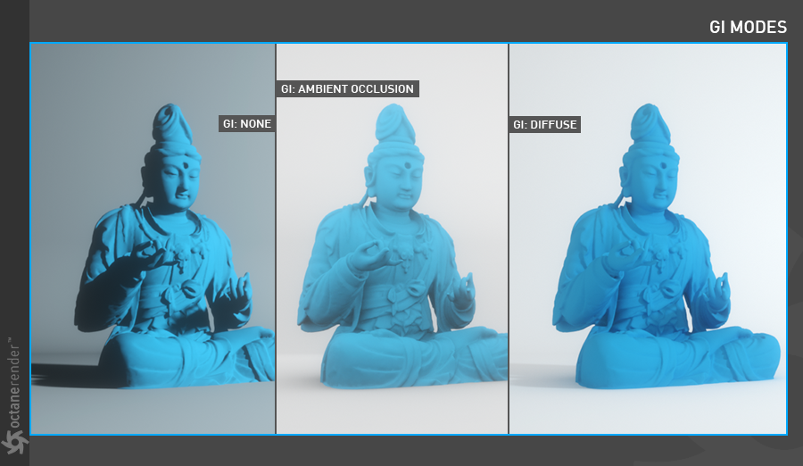
Figure 3: A comparison of the three types of GI modes.
Controls how many times a ray is refracted after hitting a surface without losing its energy. Zero means that the ray does not hit the surface and can not continue on the path (reflect or refract). if it is greater than zero, it continues on its way through the surface and refracts until it loses its energy. Higher numbers mean higher render times but more color bleeding and more details in transparent materials. Low numbers can introduce artifacts or turn some refractions into pure black (figure 4).
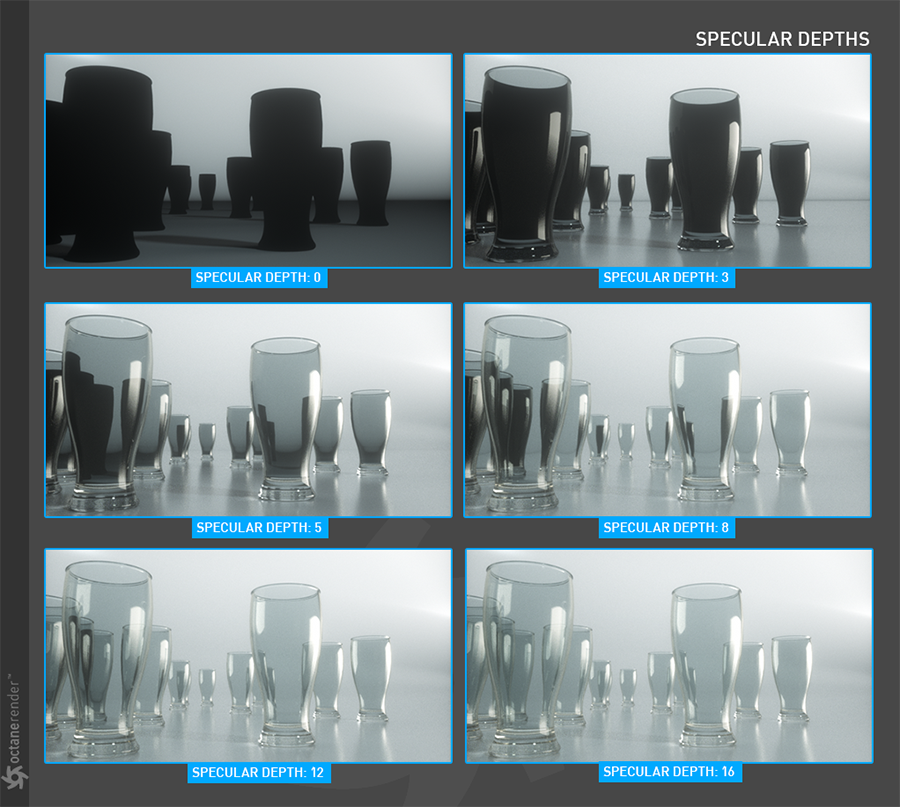
Figure 4: A comparison of different Specular Depths.
Controls how many times a ray is reflected after hitting a surface. Zero means that the ray does not hit the surface and can not continue on its path (reflect or refract). When it is greater than zero, it hits the surface and continues to be the same as the angle of incidence, so the reflection occurs. Higher numbers mean higher render time. Low numbers (under 4) can introduce artifacts, or turn some reflections into pure black (figure 5).
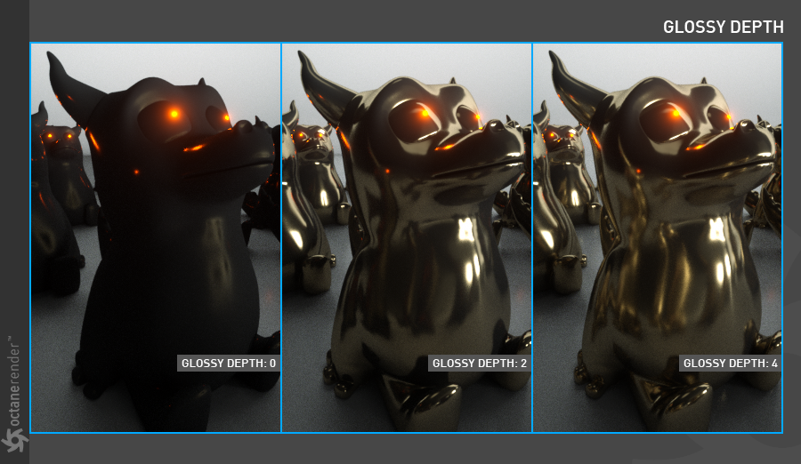
Figure 5: A comparison of different Glossy Depths.
Gives the maximum number of diffuse reflections if GI Mode is set to Diffuse. 3-5 is enough for the most scenarios (figure 6).
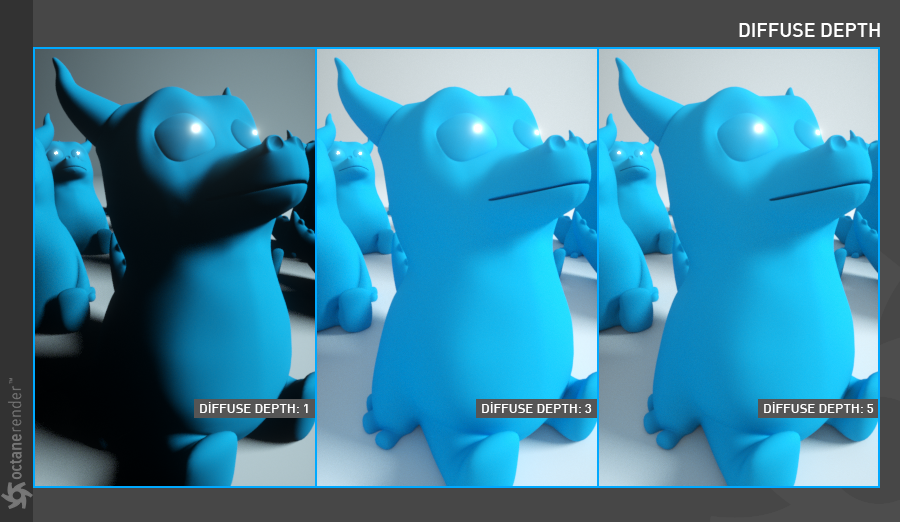
Figure 6: A comparison of different Diffuse Depths.
Ray Epsilon
The distance between the geometry and the light ray when calculating ray intersections for lighting and shadowing. Larger values push rays away from the geometry surface. Lower values are more accurate, but can cause artifacts on large or distant objects. Ray Epsilon is similar to raytracing bias in other rendering engines. Adjust Ray Epsilon to reduce artifacts in large scale scenes (Figure 7).
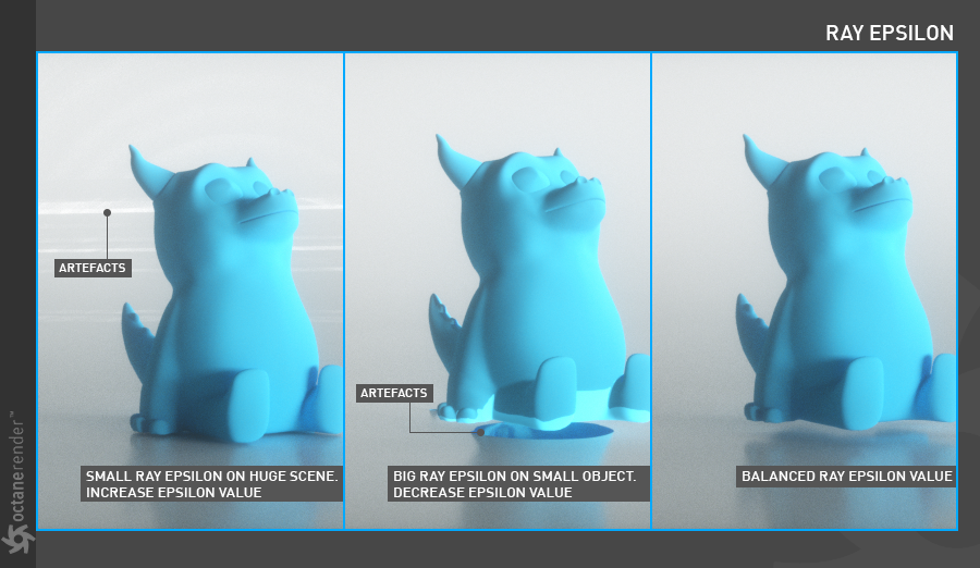
Figure 7: A comparison of different Ray Epsilon Depths.
Filter Size
Sets the filter size in terms of pixels. This can improve aliasing artifacts in the render. However, if the filter is set too high, the image can become blurry (figure 8).
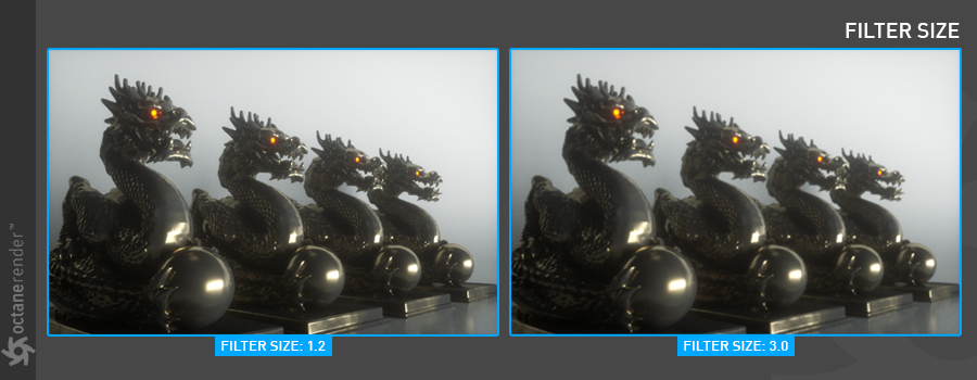
Figure 8: A comparison of different Filter Size amounts.
AO Distance
Controls the distance of the ambient occlusion shadowing spread. This setting should be adjusted in order to achieve realistic results depending on the scale of the objects in the scene. For example a small value is more appropriate for small objects such as toys and larger values for an object such as a house (figure 9).
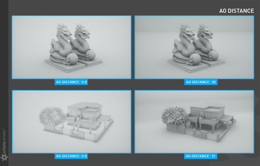
Figure 9: A comparison of different AO Distances on various scene elements.
Alpha Shadows
Allows any object with transparency (specular materials, materials with opacity settings, and alpha channels) to cast a shadow accordingly instead of behaving as a solid object (figure 10).
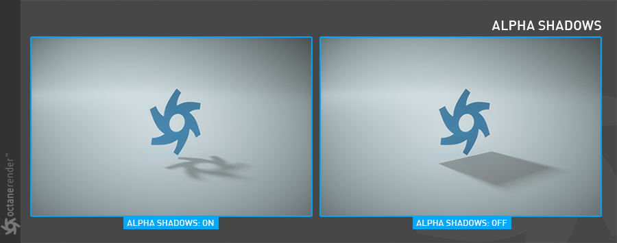
Figure 10: Alpha Shadows on and off for a scene element.
Irradiance Mode
This setting works similar to clay mode, but is only applied to the first bounce, disables bump and makes samples that are blocked by back faces transparent.
This option removes the background (for example daylight or any sky background) and renders it as transparent (zero alpha). This is useful for compositing the render over another image (figure 11).
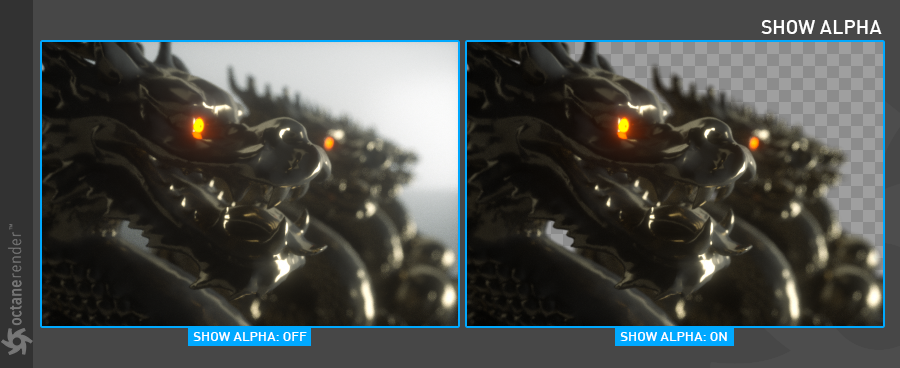
Figure 11: Removing the background from a rendering using the Alpha Channel option.
Keep Environment
This option is used in conjunction with the Alpha Channel setting. It allows the background to be rendered with zero alpha but it's still visible in the final render (figure 12). This allows even further flexibility in compositing software.
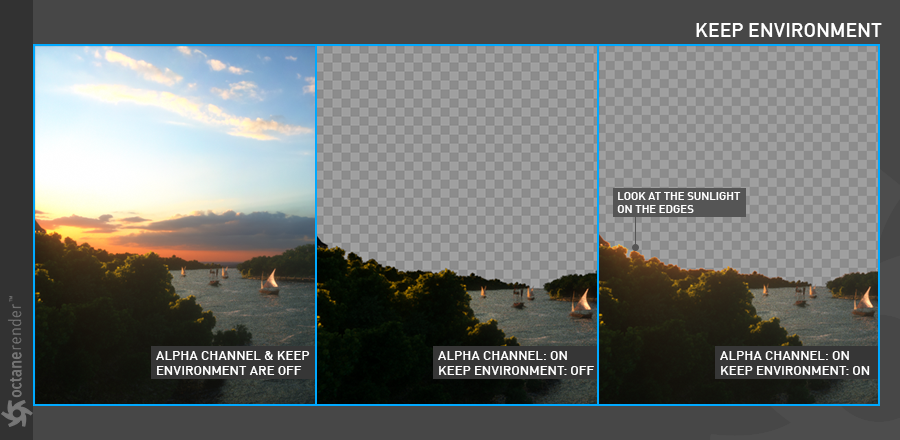
Figure 12: Using the Keep Environment option to cast background illumination onto foreground elements.
Path term. power
This parameter provides a system where users can tweak samples/second vs. convergence (how fast noise vanishes). Increasing this value will cause the kernels to keep paths shorter and spend less time on dark areas (which means they stay noisy longer) but may increase samples/second. Reducing this value will cause kernels to trace longer paths on average and spend more time on dark areas. In short, high values increases the render speed but may lead to higher noise in dark areas.
Coherent Ratio
When the coherent mode is turned on, the picture is quickly noise-free, but the negative side of the feature is flickering blotch effect in animation output. It is primarily used to develop test animations quickly (figure 13).
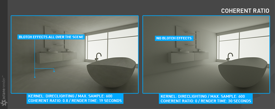
Figure 13: Comparison of different Coherent Ratio values.
Static Noise
Keeps noise patterns static between rendered frames in a sequence when enabled. Note that the noise is fully static as long as the same GPUThe GPU is responsible for displaying graphical elements on a computer display. The GPU plays a key role in the Octane rendering process as the CUDA cores are utilized during the rendering process. architecture is being used for rendering. Different architectures will produce slightly different numerical errors which manifest as small differences in the noise pattern.
Parallel Samples
Controls how many samples are calculated in parallel. Smaller values require less memory to store the sample states but may cause the render to be a bit slower. High values require more memory but can reduce render time. The change in performance depends on the scene and the GPU architecture. As illustrated in the picture below, more VRAM usage is shortening the render time (figure 14). If you have a lot of VRAM, be sure to use this option.
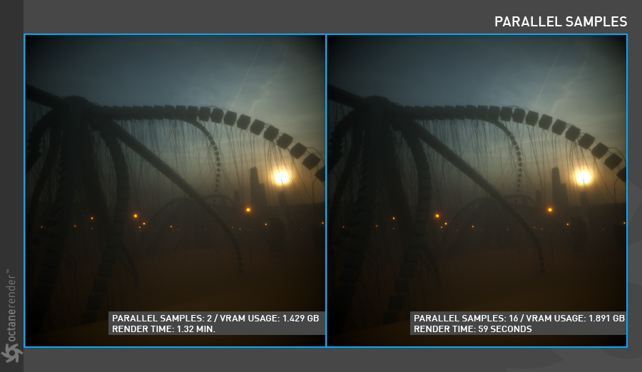
Figure 14: Parallel Samples effect on VRAM usage.
Max. Tile Samples
This controls the number of samples per pixel that Octane will render until it takes the result and stores it in the film buffer. A higher number means that results arrive less often at the film buffer, but reduce the CPU overhead during rendering and as a consequence can improve performance.
Minimize Net Traffic
Distributes only the same tile to the net render slaves until the max samples/pixel has been reached for that tile and only then will the next tile is distributed to slaves when enabled. Work done by local GPUs is not affected by this option. This way a slave can merge all its results into the same cached tile until the master switches to a different tile.
Adaptive SamplingA method of sampling that determines if areas of a rendering require more sampling than other areas instead of sampling the entire rendering equally.
A method of sampling that determines if areas of a rendering require more sampling than other areas instead of sampling the entire rendering equally (figure 15). In Octane, Adaptive Sampling disables sampling for pixels that have reached a specified noise level. With adaptive sampling, Octane is able to stop rendering on areas which no longer need to be rendered thus, freeing more GPU power to render pixels that still need noise reduction. This allows for the maximum samplesto be quite high (even more than 30,000) and then relying on the adaptive sampling to figure out which pixels actually need that many samples and which don't.
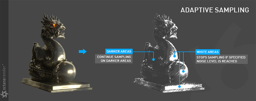
Figure 15: Using Adaptive Sampling to reduce noise in certain areas of a rendered image.
Noise threshold
Specifies the smallest relative noise level. When the noise estimate of a pixel becomes less than this value, sampling will be switched off for this pixel. Good values are in the range of 0.01 - 0.03. The default is 0.02, which is fairly clean. This is the most important part of Adaptive Sampling process. The effective processing of the adaptive sample depends on the structure of a scene's settings. Tthe Noise Mask visualizer can play a crucial part during the rendering process. If there are dark places in a scene and those areas are green, then there is a problem. In this case, the noise threshold setting will need to be adjusted. The following picture shows the correct and incorrect Noise mask (figure 16).
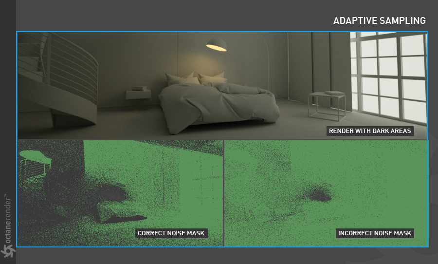
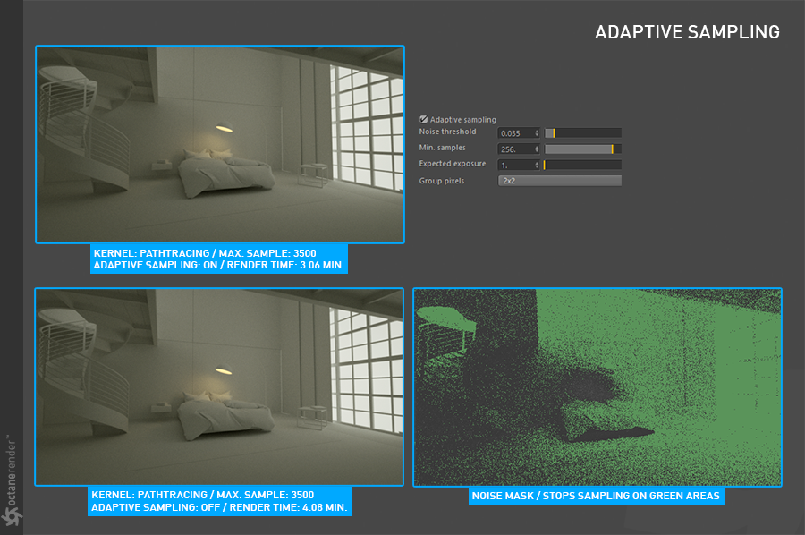
Figure 16: Using the Noise Mask visualizer to determine appropriate Noise Threshold settings.
Min. adaptive samples
Specifies the minimum samples that must have been calculated before Adaptive Sampling kicks in. The reason for this option is the fact that the noise estimate of a pixel is just an estimate with a fairly large initial error. The higher the noise threshold setting, the higher the min. samples need to be to avoid artifacts.
Pixel grouping
Specifies the number of pixels that are handled together. Iif all pixels of a group have reached the specified noise level, sampling will stop for all of these pixels.
Expected Exposure
The expected exposure should be approximately the same value as the exposure in the Octane Imager or 0 to ignore these settings. The default value is 0. This parameter is used by Adaptive Sampling to determine the pixels that are bright and those that are dark - which depends on the exposure setting in the Octane Imager. If the value is not 0, Adaptive Sampling will tweak/reduce the noise estimate of very dark areas of the image. It also will also increase the minimum adaptive samples limit for very dark areas, because very dark areas tend to find paths to light sources irregularly resulting in an otherwise overly optimistic noise estimate.
Toon shadow ambient
This is used for setting default toon ambient light color.
Pathtracing is an advanced "unbiased" render method. With this method, a rendering can obtain photorealistic quality with physical certainty. Pathtracing may cause problems in some small light sources or it may not calculate full efficiency in the case of caustic reflections. In such cases, the PMC Kernel should be used. Unfortunately, the drawback is that this method increases render times considerable over the Direct Lighting Kernel.
The various Kernels share certain parameters, likewise, many parameters are specific to individual Kernels. If a parameter is specific to a certain Kernel, it will be grayed out for all the other Kernel types. Pathtracing, for instance, introduces two parameters not available with the Direct Lighting Kernel; Caustic blur and GI Clamp. These two options are explained below (figure 17).
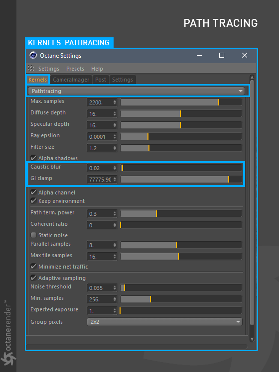
Figure 17: The Caustic Blur and GI Clamp parameters introduced when the Pathtracing Kernel is selected.
Caustic Blur
This feature is only active in Pathtracing and PMC Kernel. This parameter sets the caustic reflections to render sharp or soft. A low value will make the caustics look sharp. High values will make the caustics begin to appear blurry (figure 18).
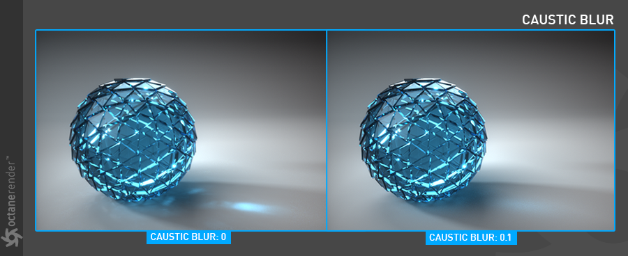
Figure 18: Adjusting the Caustic Blur values.
GI Clamp
Clamps the contribution for each path to the specified value. By reducing the GI clamp value, the amount of fireflies caused by sparse but very strongly contributing paths can be eliminated from a rendering. Caustic blur, on the other hand, reduces noise by blurring caustics, but conserves energy.
PMC Kernel
The PMC Kernel is a custom mutating unbiased kernel designed specifically for GPU rendering. Rendering with PMC creates physically accurate lighting and caustic effects and generally produces the highest quality result but can also take the most time to render depending on the scene. The options specific to the PMC Kernel are explained below (figure 19).
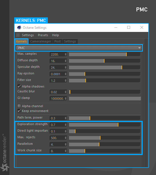
Figure 19: The PMC-specific Kernel options.
Exploration Strength
Specifies how long the kernel investigates good paths before it tries to find a new path. Low values can create a noisy image while larger values can create a splotchy image (figure 20).
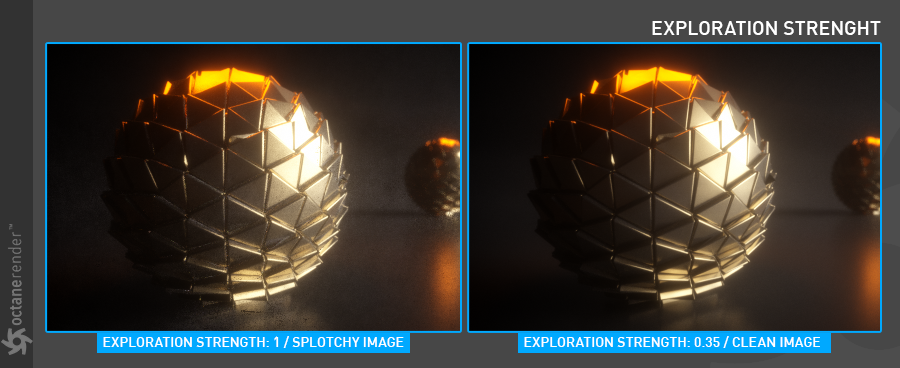
Figure 20: Comparison of different Exploration Strength values.
Direct Light Importance
Causes the kernel to prioritize ray tracing paths with indirect light. For example, sunlight through a window that creates a bright spot on the floor. When direct light importance is set to a value of 1, the kernel will sample this area more and reduce noise around the bright spot. If the direct light importance is reduced, the PMC Kernel reduces its efforts to sample that bright area and focuses more on problematic areas that may be harder to render such as areas with more indirect lighting.
Max. Rejects
Controls the “bias” of the render. By reducing this value, the result will be more biased, but the render time will be shorter. In rendering terminology, biased renders introduce slight blurring and other less physically accurate computational techniques in order to reduce render time (figure 21).
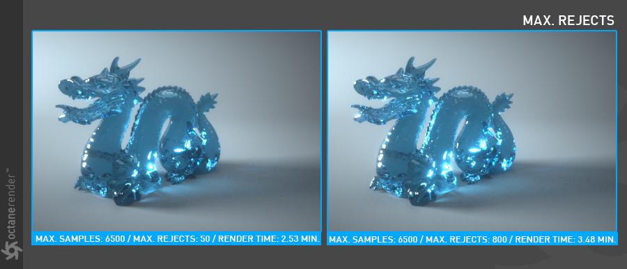
Figure 21: Increasing the Max Rejects value produces a more Biased rendering.
Parallellism
Controls how many samples are calculated in parallel. Smaller values require less memory to store the samples state but may cause the render to be a bit slower. High values require more memory but can reduce render time. The change in performance depends on the scene and the GPU architecture. Similar to parallel samples in Direct lighting or Pathtracing. If there is a lot of VRAM available, be sure to use this option (figure 22).
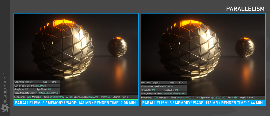
Figure 22: Comparison of different values for Parallellism.
Work Chunk Size
The number of work blocks (of 512K samples each) done per kernel run. Increasing this value increases the memory requirement on the system but does not affect memory usage and may increase render speed.
Info Channels Kernel
The Info channel kernel evaluates scene data and renders the data as color images that can be used in post processes for compositing. The options specific to the Info Channel Kernel are explained below (figure 23).
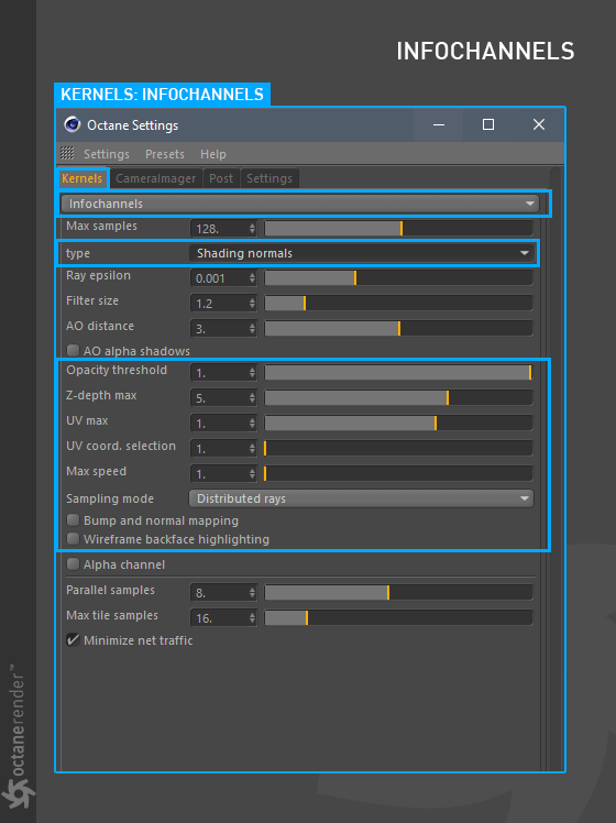
Figure 23: The options specific to the Info Channel Kernel.
Type
This parameter specifies the various passes that can be rendered and used in the compositing process (figure 24). A detailed description of these types can be found in the Render PassesRender passes allow a rendered frame to be further broken down beyond the capabilities of Render Layers. Render Passes vary among render engines but typically they allow an image to be separated into its fundamental visual components such as diffuse, ambient, specular, etc.. section.
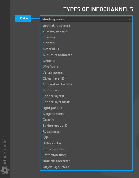
Figure 24: The list of available Info Channel types that can be rendered.
Opacity Threshold
If there is an opacity value defined for any scene materials, the opacity value can be increase or decreased with this option. It only changes the opacity value for the Info Channel output. The opacity value in the material does not change. This option does not work if the opacity value in the material is opaque.
Z-DepthA measure of object distances from the camera typically represented as a grayscale image. Max
This parameter only becomes active when Z-depth type is selected as the Info Channel. Determines the maximum depth of the Z-depth Info Channel type as shown in the picture below (figure 25).
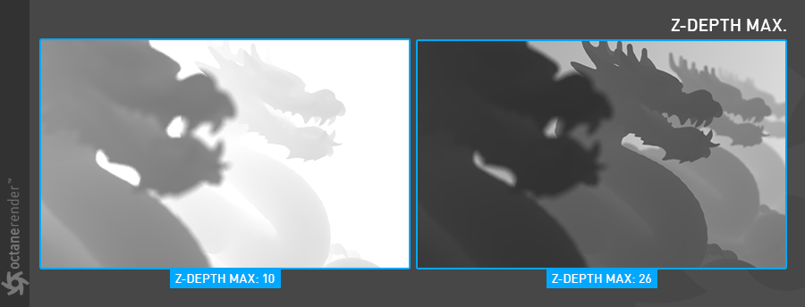
Figure 25: Setting the Z-Depth value.
UV Max
This parameter only becomes active when Texture coordinates type is selected as the Info Channel. Sets the maximum value that can be shown for the texture UV coordinates (figure 26).
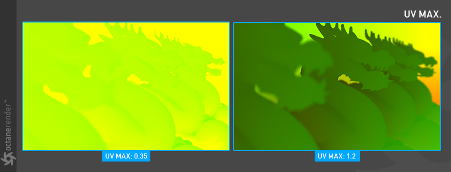
Figure 26: Setting the UV Max value.
UV Coord Selection
Determines which set of UV coordinates to use.
Max Speed
Speed mapped to the maximum intensity in the motion vector channel. A value of 1 means a maximum movement of 1 screen width in the shutter interval.
Sampling Mode
This option has three sub-menus:
Bump and Normal Mapping
If bump or normal map channels are used with materials, this option determines whether they appear or not in the Info Channel rendering (figure 27).
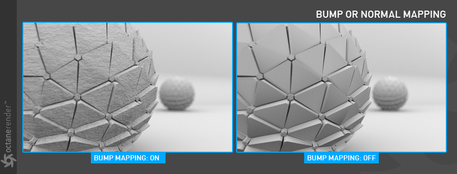
Figure 27: Activating Bump mapping in the Info Channel rendering.
Wireframe Backface Highlighting
Highlights back faces of the wireframe output. The Wireframe Info Channel needs to be selected for this feature to be active.