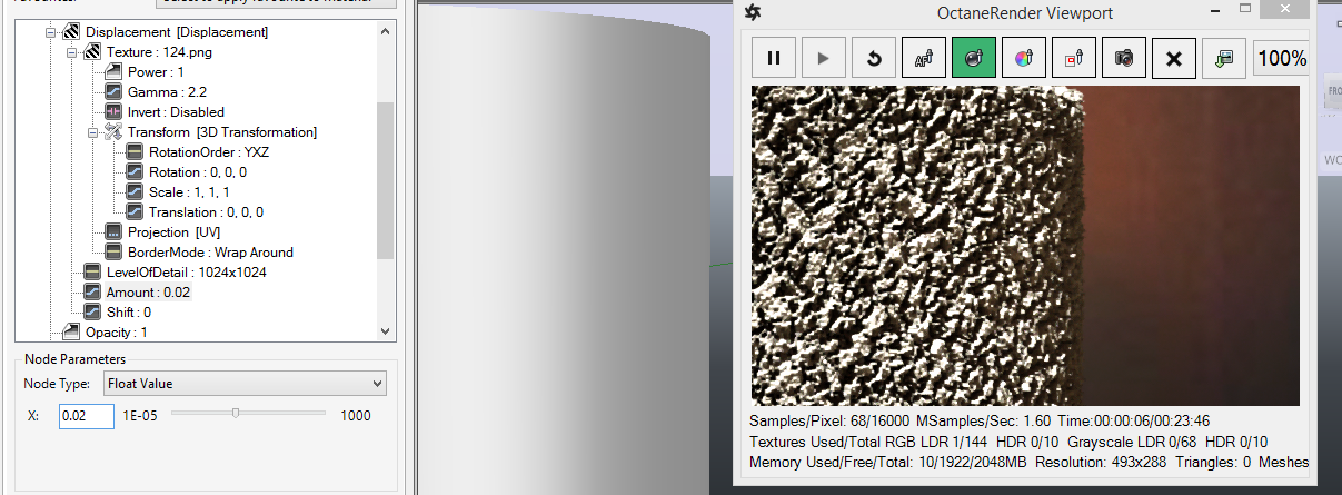
This is a new pin on each Octane MaterialThe representation of the surface or volume properties of an object. type. Change the Displacement pin type to Displacement and assign a Grayscale Image node to the Texture pin and load the displacement map. Use caution when setting thing displacement amount – since high amounts may cause a video card error. It is highly recommended that you use 16 bit displacement maps (since 8 bit maps do not provide the granularity required for high quality renders).
NOTE: You may need to adjust the Kernel->Ray Epsilon to ensure there is no self-shadowing from displacement geometry.
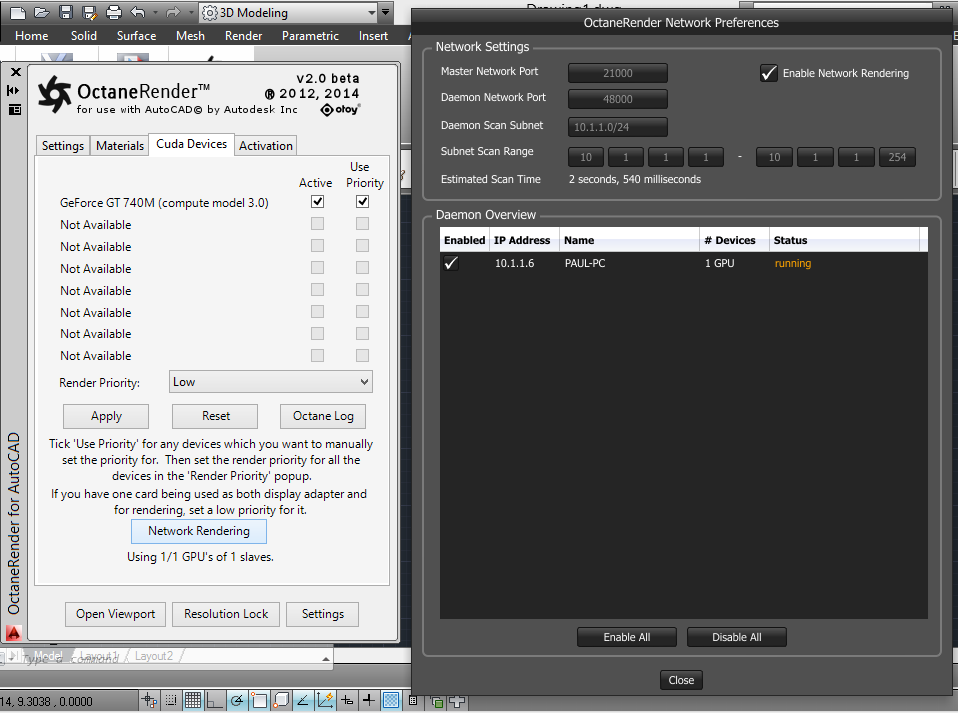
Fully supported, and available from the Device tab of the plugin (Network Rendering button). Setup the Slave PC as per the Octane Standalone instructions, the activate in the Network Render window. To do this, untick Enable Network Rendering, select the appropriate Daemon Scan Subnet (may only be one option), tick Enable Network Rendering, then tick the Slave PC which is found on the network that you want to use. Subsequent rendering in the plugin will use that slave PC.
IMPORTANT: The Octane version for the Slave must be the same version as the plugin you are using (ie. if you are using version 2.0.10.x of the plugin, you must run the slave for Octane 2.0.10).
Random Color Texture
Not useable – since the AutoCAD plugin does not support Octane scattering.
HDRIAn image which presents more than 8 bit per color channel unlike most common image formats. & Sun
This is supported through the Octane Daylight Environment node. Connect an IBL texturemap to the “Texture” pin to enable this option.

Ambient Occlusion
This is a new render type in the Info Channel Kernel. If using this, enable the AlphaChannel pin.
Normal Space Position Type
This is a new Position Type that is used for IESAn IES light is the lighting information representing the real-world lighting values for specific light fixtures. For more information, visit http://www.ies.org/lighting/. lighting – which when used, directs the IES light in the direction of the normal of the emitter geometry. For best results with IES lights, use a Spherical Projection, and set the Position Type to Normal Space.
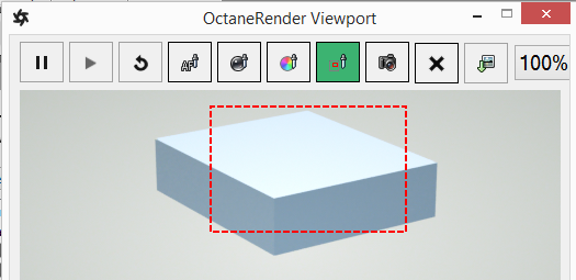
Render Region
Enable the selection (via mouse dragging in the Viewport) of a render region by clicking the Render Region button. All other pick functions (focus, material, white balance) are disabled whilst Render Region is enabled.
Perspective Correction
Enabling this camera option renders vertical lines parallel. This requires the Octane Camera Up Vector to be directly “up”, so you will need to manually override the Camera “Up” pin to be 0, 1, 0. Moving the AutoCAD camera will reset the Up vector to match the AutoCAD Viewport.
Edge Rounding
Not currently supported – since AutoCAD does not provided welded vertices on geometry items.
Strand Hair
Not currently supported – since AutoCAD does not support vertex strand geometry items.
Subdivision
Not currently supported – since AutoCAD does not provided welded vertices on geometry items.
Not currently supported – since AutoCAD does not have an object animation system.