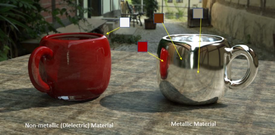
Metallic materials are highly reflective materials that have colored reflections (highlights) that come off at different wavelengths and its reflections are propagated by a full color specular map.
Figure 1: Metallic materials have full-colored reflections
OctaneRender has a Glossy materialUsed for shiny materials such as plastics or metals. node, which by default emulates a diffuse surface with a clear coat. This works well for plastics. A Metallic material works similar to a GlossyThe measure of how well light is reflected from a surface in the specular direction, the amount and way in which the light is spread around the specular direction, and the change in specular reflection as the specular angle changes. Used for shiny materials such as plastics or metals. material, but the way the channels are combined is more suitable to model metals.
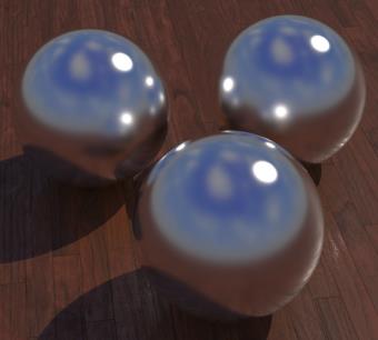
Figure 2: Left: without Fresnel effect; Right: with Fresnel effect
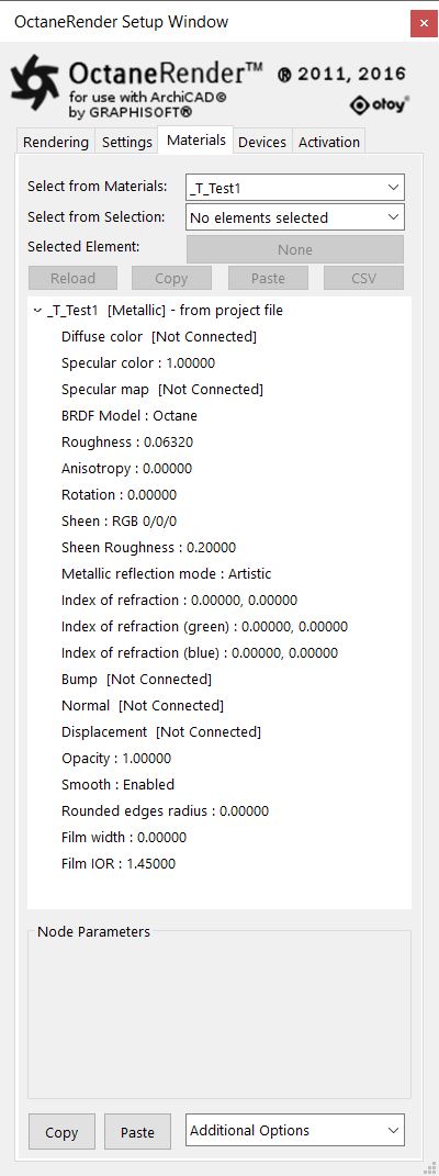
Figure 3: The attributes the Metallic Material Node
Attributes of the Metallic MaterialThe representation of the surface or volume properties of an object. Node:
This is the diffuse texture for the reflection channel.
This is the specular reflection channel which determines the metallic color. If the index of reflection is set to a value → 0, then the brightness of this color is adjusted so it matches the Fresnel equations.
Specular Map
This controls the blend between the diffuse and metallic reflection. The metal node has a diffuse and a specular channel. The mix between those two channels is explicitly controlled via a third texture input, usually called a specular map.
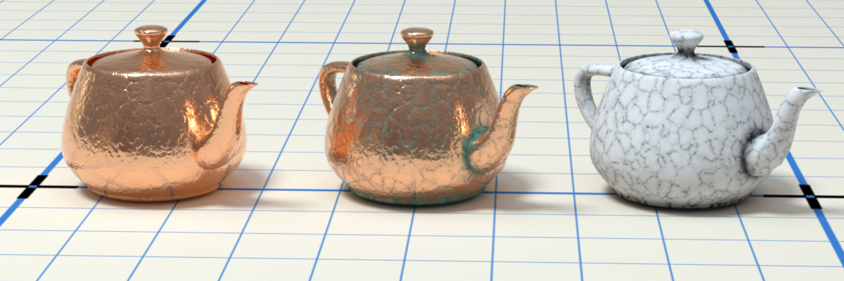
Figure 4: From left to right: Specular only, Specular and Diffuse with Specular map, visualisation of the Specular map
BRDF Model (Bidirectional Reflectance Distribution Function)
The BRDF is a function that determines the amount of light reflected from a material when light falls on it. For Metallic materials, there are four applicable BRDF Models to choose from. Each BRDF is effected by a specific geometric property - the microfacet distribution - of the surface which describes the microscopic shape (i.e. microfacet normals) of that surface and serves as a function to scale the brightness of the reflections in the BRDF. Refer to the topic on BRDF Models for more information.
|
Octane 3.07 |
Beckmann |
|
GGX |
Ward |
Figure 5: The four BRDF Models applicable to Metallic materials
Roughness
This refers to the roughness of the Specular reflection channel.
Anisotropy
This controls the uniformity of the material’s reflectance. If the reflectance changes based on the orientation or the rotation of the surface, it is said to be Anisotropic. And likewise, if the reflectance is uniform in all directions and does not change based on the orientation or the rotation of the surface, it is said to be Isotropic. By default, this attribute is 0, and sets the Metallic material initially as Isotropic. Non-zero values mean that the material will exhibit Anisotropic reflectance, where -1 is horizontal and 1 is vertical.
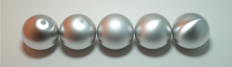
Figure 6: Anisotropic roughness exemplified in materials like brushed metal
Rotation
This refers to the rotation of the anisotropic specular reflection channel.
Sheen
This is the color of the subtle lustre on the surface of the material.
Sheen Roughness
This is the roughness channel for the sheen that is present on metallic and glossy materials.
IOR Mode
This controls the Complex IOR settings of the Metallic material. By default, metals use the Schlick approximation for the Fresnel effect. For a more precise falloff, a complex IOR can be entered (commonly known as n and k values). When a complex IOR is set up, the metallic color will get scaled so the brightness matches the Fresnel falloff for that IOR.
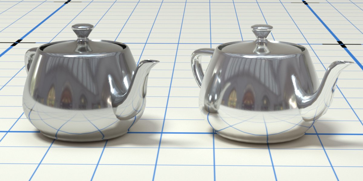
Figure 7: Left: Chrome (n = 2.710, k=4.178); right: Aluminium (n = 0.930, k=6.294)
Metallic Reflection Mode
This changes how the reflectivity is calculated.
Index of Refraction
Complex-valued index of refraction (n-k*i) controlling the Fresnel effect of the specular reflection where n is the refractive index and k is the attenuation or extinction coefficient. For RGB mode, the IOR for red light (650nm).
Index of Refraction (green)
For RGB mode, the IOR for red light (550nm).
Index of Refraction (blue)
For RGB mode, the IOR for red light (450nm).
Bump
This is the Bump channel, which is used to simulate a relief using a greyscale texture interpreted as a height map.
Normal
This is the Normal channel, which is used to distort normals based on an RGB image.
This is the Displacement channel, which is used to create highly detailed geometry with a low memory footprint. The Effects category covers Displacement mapping in more detail.
Opacity
This is the Opacity channel, which controls the transparency of the toon material via greyscale texture.
Smooth
This is a boolean value to enable or disable normal interpolation. If normal interpolation is disabled, triangle meshes will appear faceted.
Rounded Edges Radius
This is the radius of the rounded edges that are rendered as a shading effect.
Film Width
Film Width simulates the look of a thin film of material on the surface. This is useful when you want to create an effect such as the rainbow colors that appear on the surface of an oil slick. Larger values increase the strength of the effect.
Film IOR
The Film IOR controls the Index of Refraction of the thin film, use this option to adjust the colors visible in the film.
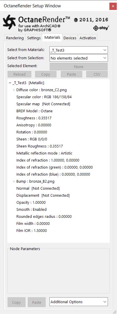
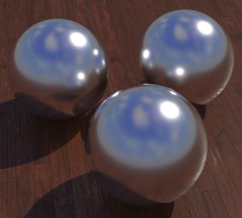
Figures 8: Left: parameters for the objects on the left; right: parameters for the objects on the right.
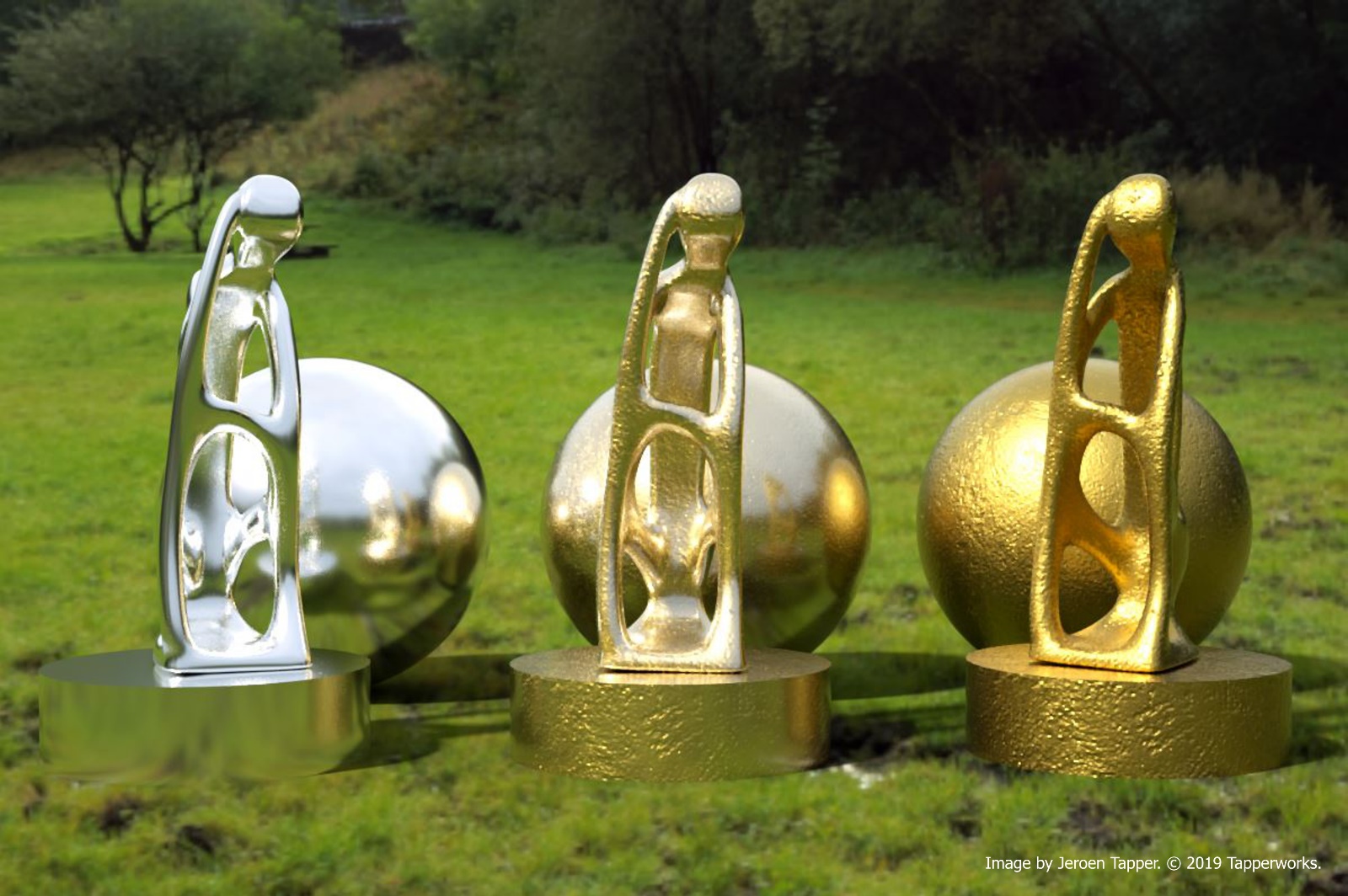
Figures 9: The objects in the middle do have a Mix materialUsed to mix any two material types. of the left and right Metallic materials.