Open topic with navigation
Glossy Material
The is used for shiny materials such as plastics or metals.
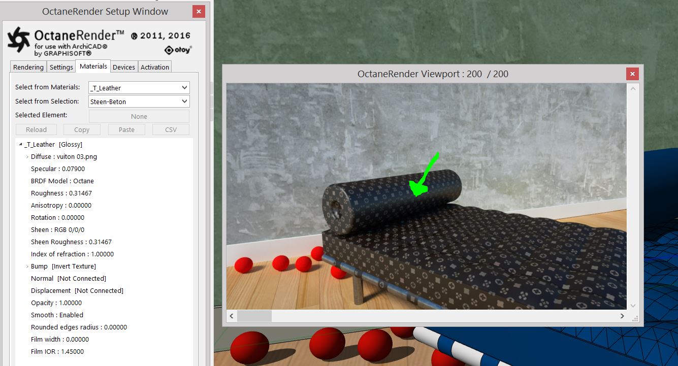
materials have the following parameters to adjust:
Glossy Parameters:
- - Gives the material its color, which is referred to as base color or albedo. You can set Diffuse color by using a value, or by connecting a texture (procedural or image-based).
- Specularity - Determines the intensity for specular reflections on the surface. This parameter accepts color, values, or textures. In most cases, specular highlights are white or colorless. However, to simulate metallic surfaces, you should tint the specular color using a color similar to the Diffuse parameter, like the bright yellow-orange highlights seen on a polished copper kettle. A Glossy node with a black Diffuse color, a Roughness of 0, and an Index of 0 produces a perfect mirror (Figure 2).
- BRDF Model - The BRDF (Bidirectional Reflectance Distribution Function) determines the amount of light that a material reflects when light falls on it. For Glossy materials, you can choose from four BRDF models. Specific geometric properties (the micro-facet distribution) of the surface affects each BRDF, which describes the surface's microscopic shape (i.e. micro-facet normals) and scales the brightness of the BRDF's reflections. Refer to the topic on BRDF Models for more information.
|

Octane 3.07
|
Beckmann
|
|
GGX
|
Ward
|
Figure above: The four BRDF Models applicable to Glossy materials
- Roughness - Determines how much reflection spreads across the surface - also known as reflection blur. This parameter accepts a value, color, or texture map (Procedural or Image). A value of 0 simulates a perfect, smooth reflective surface like a mirror. Increasing the value simulates micro-facets in the surface, which causes reflective highlights to spread. To create a worn plastic look, increase the Roughness value.
- Anisotropy - Controls the material's reflectance uniformity. Reflectance changes based on surface orientation or rotation is anisotropic. If the reflectance is uniform in all directions and doesn't change based on the surface's orientation or rotation, then it is isotropic. This parameter's default value is 0, which sets the metallic material as isotropic. Non-zero values mean the material exhibits anisotropic reflectance, where -1 is horizontal and 1 is vertical.
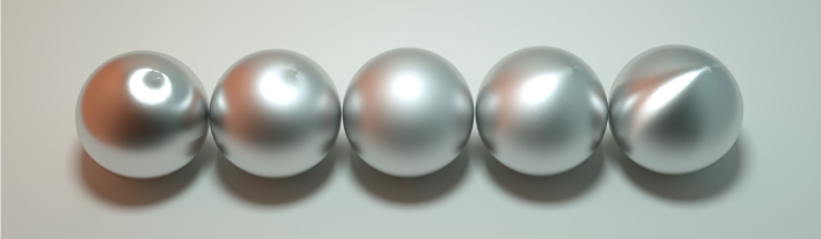
Figure above: Anisotropic roughness exemplified in materials like brushed metal
- Rotation- The rotation of the anisotropic Specular reflection channel.
- Sheen- The material's sheen color.
- Sheen Roughness- Roughness channel for the sheen present on Metallic and Glossy materials.
- Index of Refraction- Determines the reflection strength on the surface based on Fresnel's law. With a value greater than 1, reflection is strongest on the surface parts that turn away from the viewer's angle (grazing angles), while the reflection appears weaker on the surface parts perpendicular to the viewing angle. This results in a more realistic-looking surface. With a value lower than 1, the Fresnel effect is disabled, and the reflection color appears as a uniform color across the highlight. The Specular channel's color determines the reflective highlight's color.
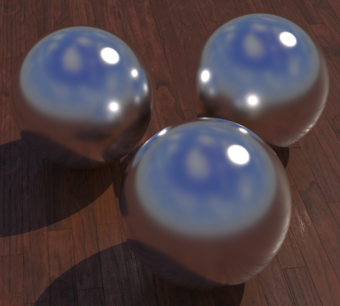
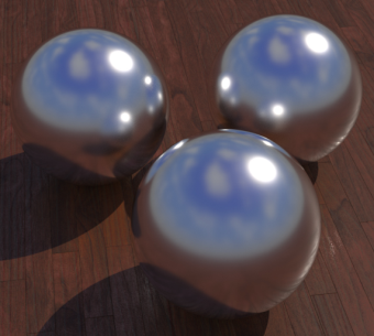
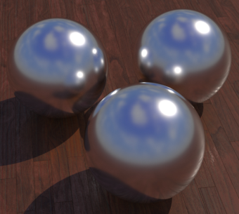
In the following examples, the six balls have a roughness of 0, 0.2, 0.4, 0.6, 0.8, 1.0 (left to right) and only the Specular value and Index of Refraction parameters are modified for each rendered image (see Figure 3).
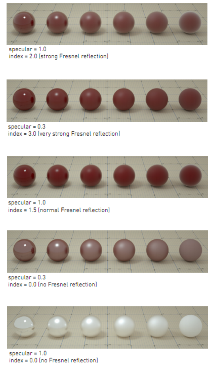
Figure above: Spheres rendered using different settings for specular and index
- Bump- Creates fine details on material surfaces using a Procedural or Image texture. When you connect a Greyscale image texture to this parameter, light areas appear as protruding bumps, and dark areas appear as indentations. You can adjust the Bump map strength by setting the Power or values on the Greyscale image texture node. The Texture Overview category covers these attributes in more detail.
- Normal- Creates the look of fine detail on the surface. A Normal map is a special type of image texture that uses red, green, and blue color values to perturb the normals of the surface at render time, thus giving the appearance of added detail. They can be more accurate than Bump maps, but require specific software, such as ZBrush®, Mudbox®, Substance Designer, xNormalTM, or others to generate. to load a full color Normal map, set the Normal channel to the RGB Image data type. Note that Normal maps take precedence over Bump maps, so you cannot use a Normal map and a Bump map at the same time.
- - Adjusts surface vertices' height at render time using a Texture map. Displacement maps differ from Bump or Normal maps by having the texture alter the geometry, as opposed to creating the appearance of detail on the surface. Displacement mapping is more computationally expensive than Bump or Normal mapping, but results are more realistic, especially along the surface silhouette. The Effects category covers Displacement mapping in more detail.
- Opacity- Determines what surface parts are visible in the render. Dark values indicate transparent areas, and light values indicate opaque areas. Values between light and dark create the look of semi-transparent areas. You can lower the Opacity value to fade the object's overall visibility, or you can use a Texture map to vary the surface's opacity. For example, if you want to make a simple polygon plane look like a leaf, you connect a black-and-white image of the leaf's silhouette to the Diffuse shader's Opacity channel. When you use an Image texture map, set the Data type to Alpha image if the image has an alpha channel, or Greyscale image for black-and-white images, to load an image for setting transparency. Use the image's Invert checkbox to invert the transparency regions.
- Smooth- Smooths out the transition between surface normals. When disabled, the edges between surface polygons appear sharp, giving the surface a faceted look. when enabled, the edges between polygons blend together.
- Rounded Edges Radius- Bevels the surface edges automatically at render time, without the need to alter or subdivide the geometry. This option enhances object realism by eliminating sharp edges. Higher values produce rounder edges.
- Film Width- Simulates the look of thin film material on a surface, like creating a rainbow color effect that appears on an oil slick's surface. Larger values increase the effect's strength.
- Film IOR- Controls the film Index of Refraction. This option adjusts the visible colors in the film.
Open topic with navigation